Preflight Checklist
Swift GCS includes an integrated preflight checklist, replacing paper checklists. Some steps are automated, while others require manual interaction. Each step in the GCS has an info button for help text. This manual section mirrors the GCS checklist and offers supplementary information.
Always adhere to the Sapphire Performance and System Limitations.
Adherence to the preflight checklist is crucial to the safe and successful operation of the Sapphire. The preflight steps must be performed before every flight. Failure to preform a preflight step can result in a total loss of the aircraft and pose a hazard to people on the ground.
Contents
- Power Source - Ensure
- Equipment - Assemble
- Aircraft - Assemble
- Payload - Install
- Aircraft - Inspect
- Pitot Tube - Check
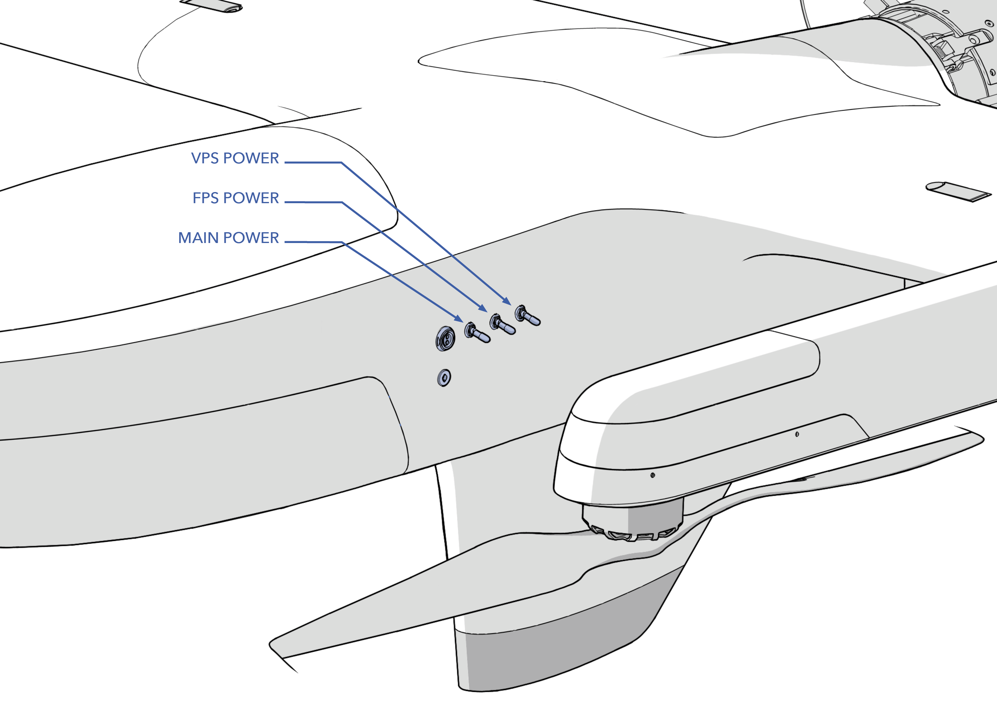
- Aircraft Switches - Off
- Aircraft - Fuel
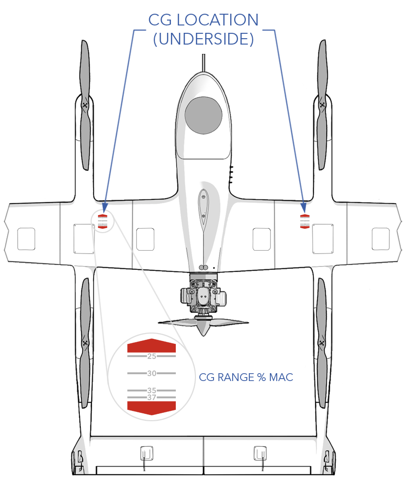
- Weight and Balance - Verify
- Avionics Battery - Connect
- Aircraft Power - On
- Shore Power - On and Connect
- Canopy - Install
- VPS Batteries - Connect
- Radio Settings - Verify
- Controller Remote Host and Model - Verify
- Autopilot - Connect
- Aircraft - Disarmed
- Firmware - Check
- Automated Parameter Checks
- Payload Power - On
- Old Mission - Clear
- Takeoff - Add
- Takeoff Heading - Add
- Mission - Create
- Landing - Add
- Rally Points - Add
- Mission - Upload
- Flight Modes - Verify
- Failsafes - Verify
- Payload Checks Complete - Verify
- Payload Power - Off
- Nav Lights - Verify
- Autopilot - Warmup
- Airspeed - Calibrate
- Compass Heading - Verify
- VPS Batteries - Warmup
- VPS Switch - Verify Off
- Mode - Auto
- Initial Waypoint - Set
- Control Surface - Unlock
- Control Surface Response - Check
- VPS Props - Clear
- VPS Motors - Test
- Mode - Manual
- Manual Surface - Check
- Throttle and Ignition - Safe
- FPS Switch - On
- Allow Disarmed Start - Enable
- FPS Prop - Clear
- Engine - Start
- Shore Power - Disconnect
- Payload Power - On
- Engine - Warmup
- Full Throttle - Check
- Idle - Check
- Mode - Auto
- VPS Switch - On
- All Personnel - Clear
- No Warnings - Verify
- Takeoff Clearance - Confirm
- Aircraft - Takeoff
Power Source - Ensure
Ensure that you have access to a power source that is capable of powering all necessary equipment throughout the entire duration of the flight.
This step applies to powering the ground support equipment. Common power sources include shore power and generators.
Ground Equipment - Assemble
Inspect and assemble the NOB, GCS, IP radio, and hand controller using the walkthrough below.
This list may change depending on your mission or aircraft configuration. At a minimum, this will include the GCS computer, IP radio, network operations box (NOB), and hand controller.

Do not use shielded ethernet cables with ground equipment.
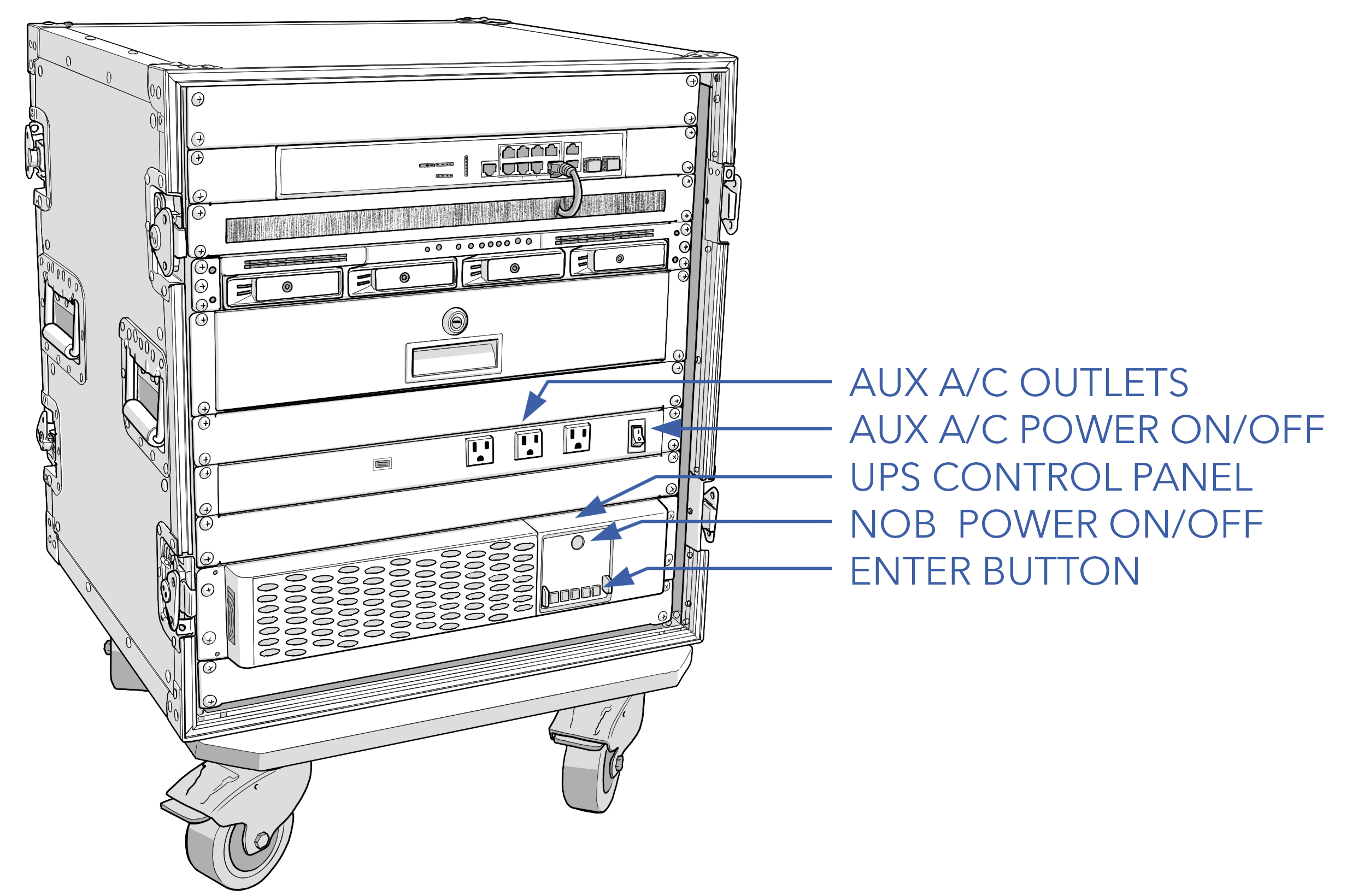
NOB
- Set the NOB on a stable, level surface.
- Unlatch and remove the front and rear covers.
- Plug the Main NOB AC Power cable into an appropriate 120VAC outlet from a generator or shore power.
- Power on the NOB by first pressing the main power button, followed by the enter button.
- Verify that the UPS has adequate battery for operations with a safety margin in the event of a power interruption. The NOB will charge the UPS batteries while plugged in.
GCS
- Plug the GCS computer into an appropriate AC outlet.
- Connect the ethernet cable into the GCS, and the opposite twist-lock end into the NOB.
- Power on the GCS.
- Verify that the screen brightness is adequate for your working conditions.
- Verify that the GCS computer has adequate battery for operations with a safety margin in the event of a power interruption.
- Launch Swift GCS software.
- Launch payload software if applicable.
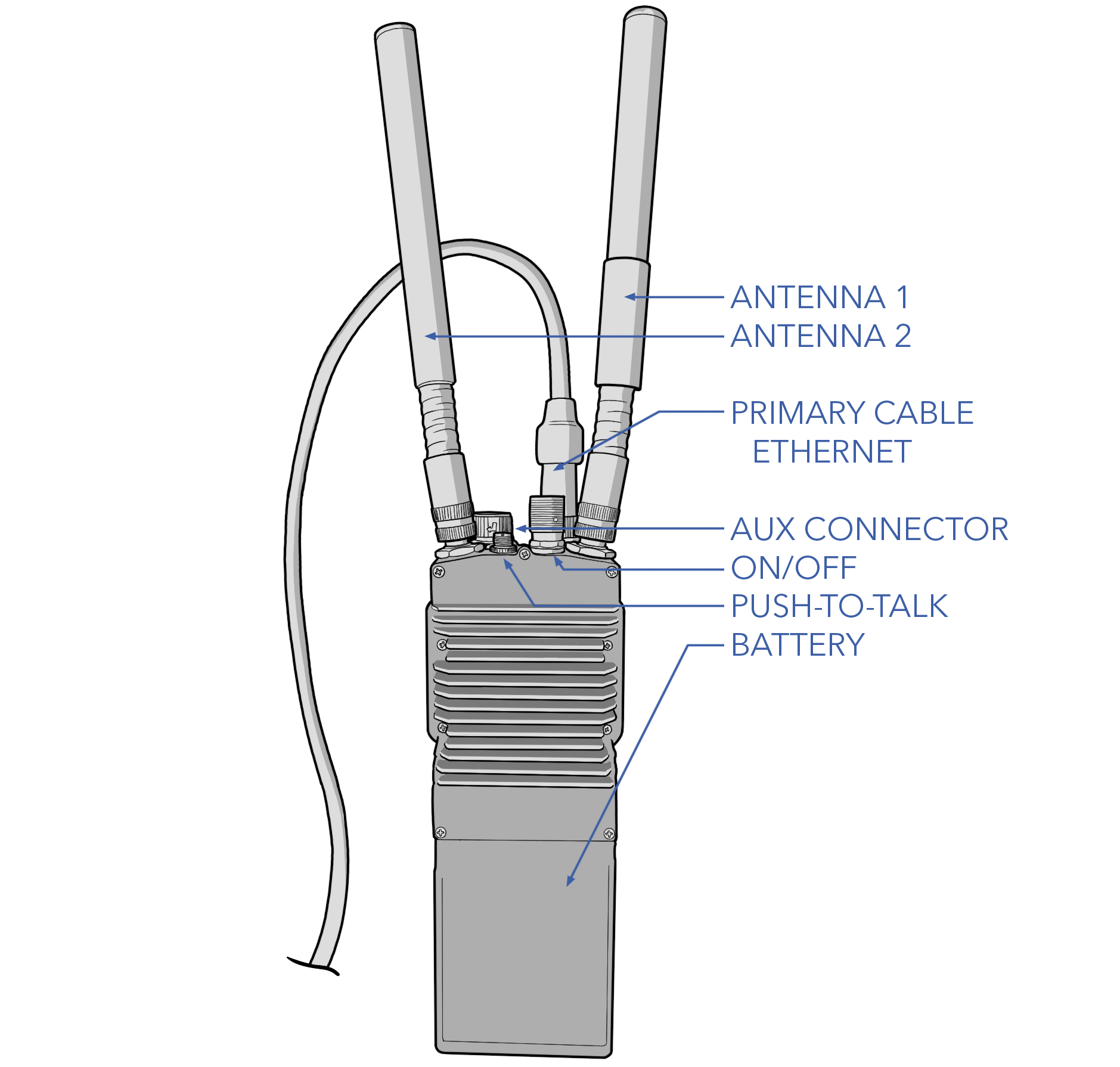
IP RADIO
- Connect the ground antennas to the radio. See the Antenna Tracker Appenix if using an antenna tracker.
- If powering the radio from the NOB, connect the battery eliminator to the radio and plug the opposite end into the NOB.
- If using battery power, connect the radio battery to the radio. Verify that the battery is sufficiently charged. A fully charged battery lasts approximately 12 hours.
- Connect the primary cable to the radio, and the opposite twist-lock end into the NOB.
- Power on the radio.
Hand Controller
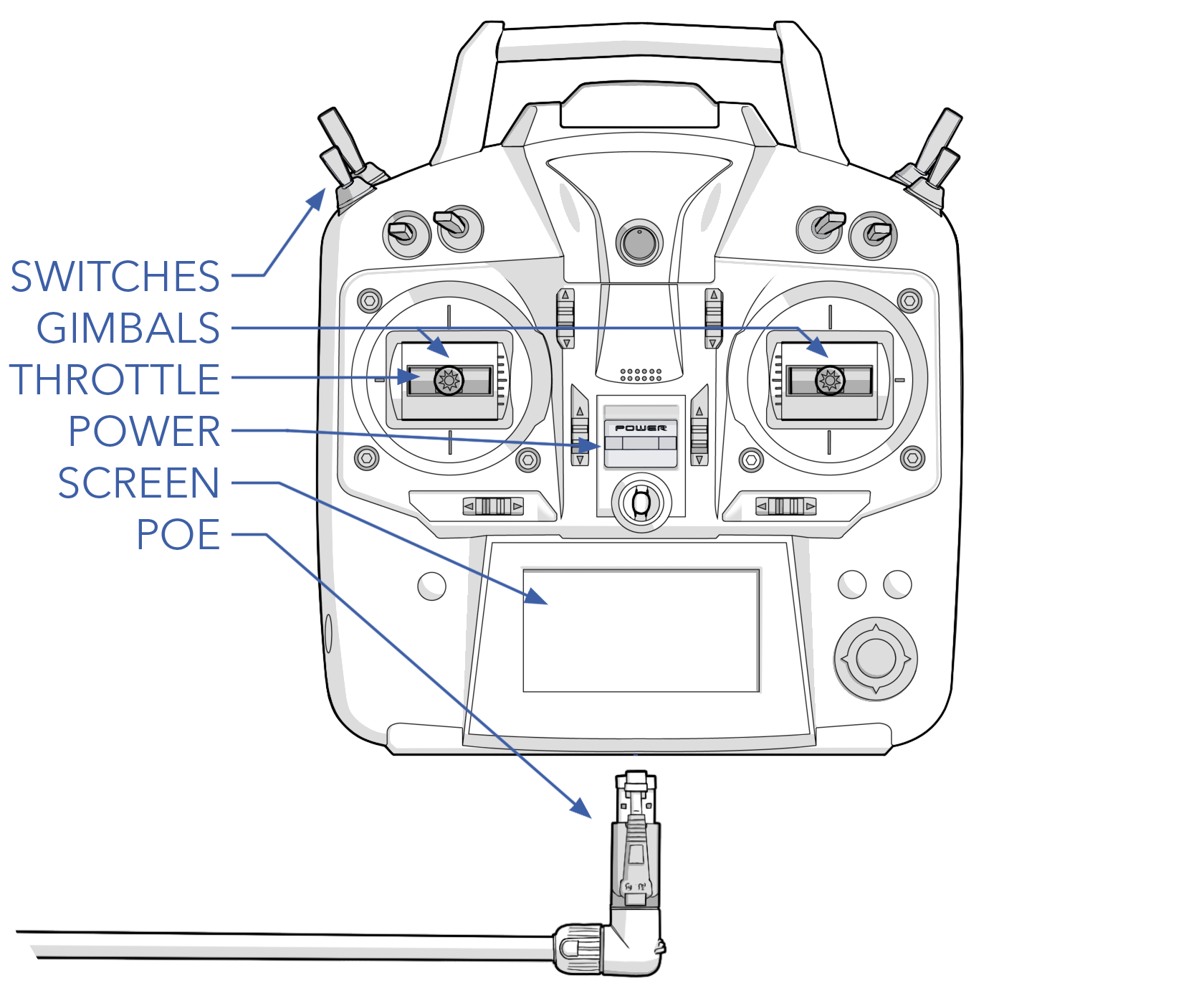
- Inspect the switches and gimbals. The switches should freely move to each position. The gimbals should move without any resistance or grinding and, with the exception of throttle, should center when released.
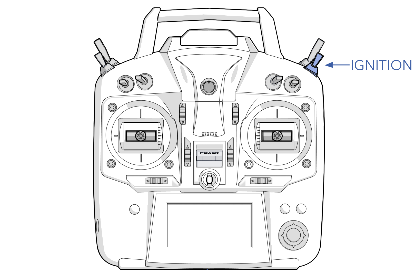
- Set the throttle stick to idle (down) and the ignition switch to OFF. The position of the remaining switches is inconsequential.
- The hand controller is a power over ethernet (POE) device and is powered by the NOB. Connect the ethernet cable into the hand controller, and the opposite twist-lock end into the NOB.
- Power on the hand controller.
- Ensure the appropriate Sapphire model is selected and displayed on the hand controller screen.
See Changing the Hand Controller Model if the correct aircraft is not selected.
APS
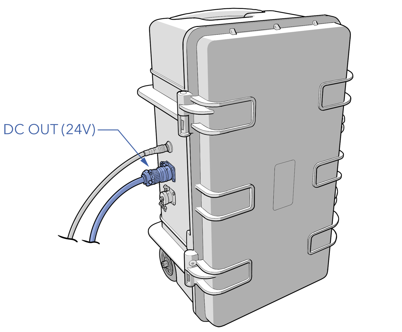
- Open the case lid and remove the shore and DC power cables.
- Power the APS on.
- Look at the voltage meter and verify the APS is charged.
- Close the case lid.
- Connect the DC power cable to the APS.
Fueler
- Fill the fueler with the appropriate gas/oil/treatment mixture and volume.
- Verify that the scale works.
- Connect the DC power cable from the APS to the fueler.
Refer to the Fueling Section for detailed fueling and mixing instructions.
Aircraft - Assemble
Follow the walkthrough to assemble the aircraft components.
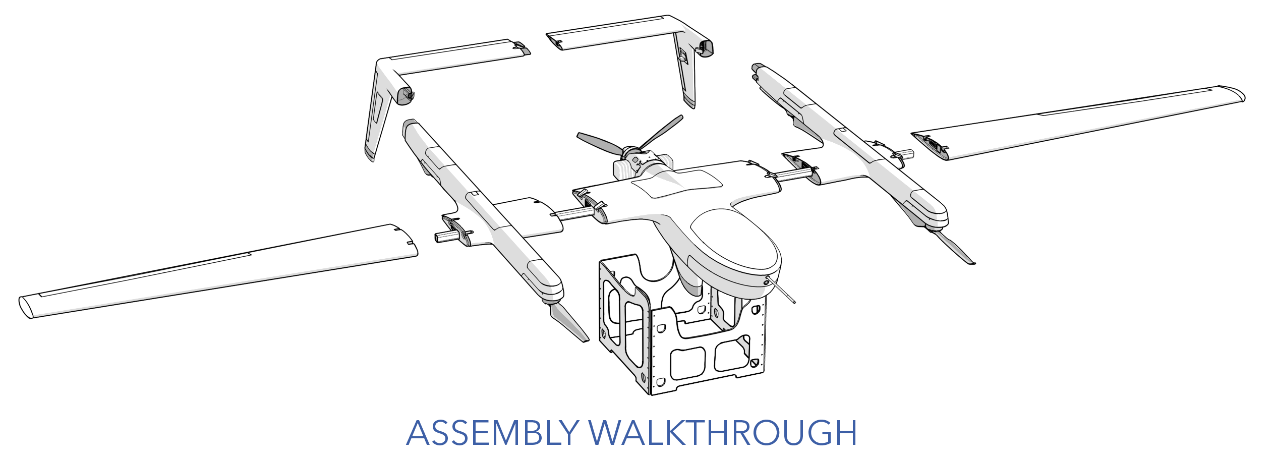
Assembly of the aircraft requires a minimum of two people.
- Remove the transport case lid.
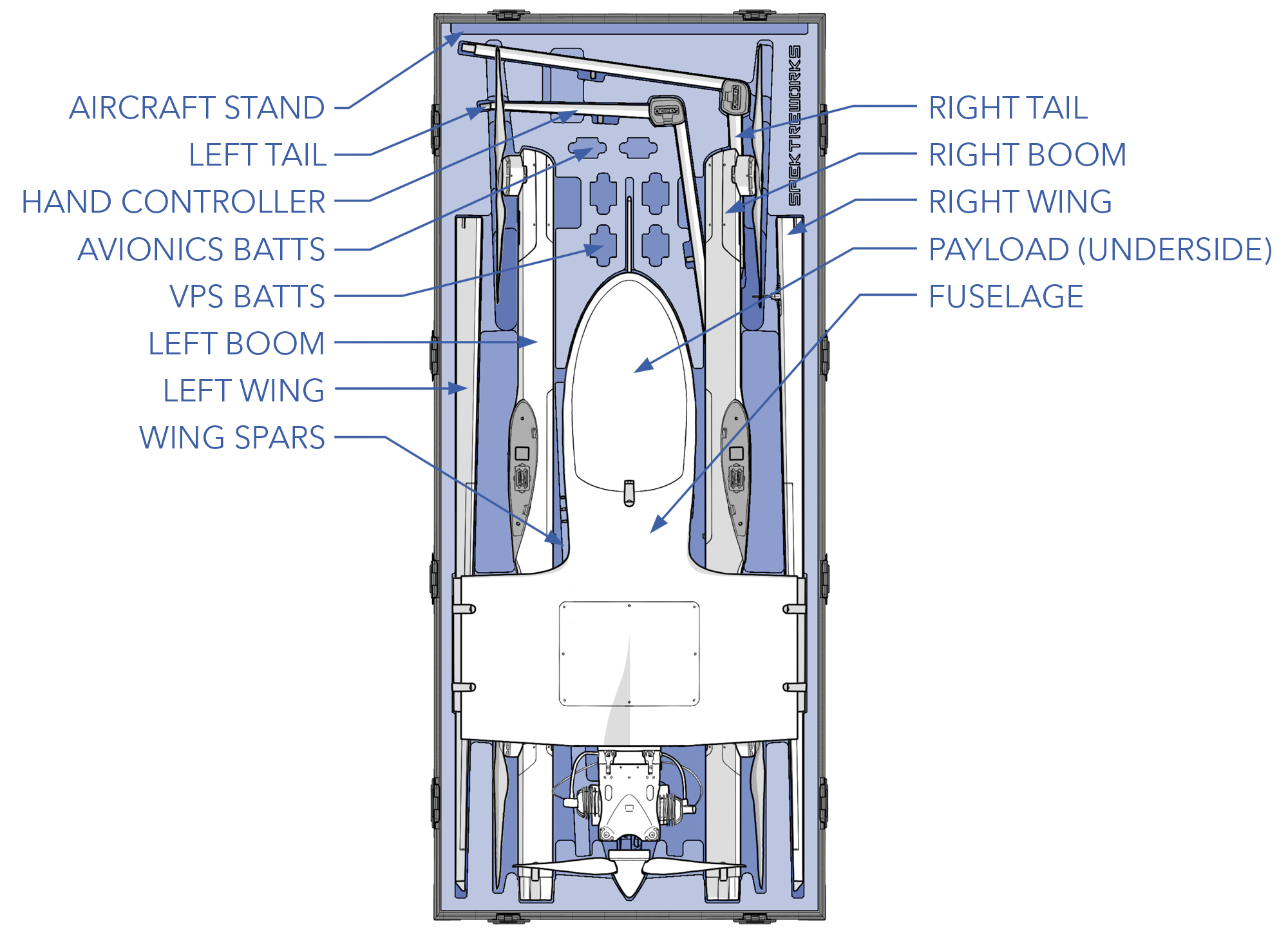
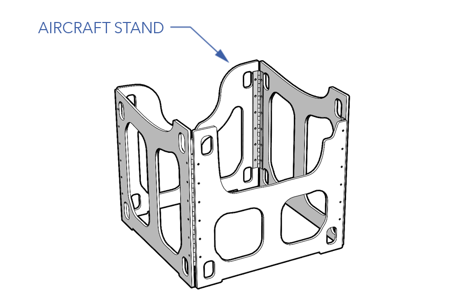
- Remove the aircraft stand from the case and place it in a clearing suitable for assembling the aircraft. An area measuring 20 x 20 feet (6 x 6 meters) is preferred.
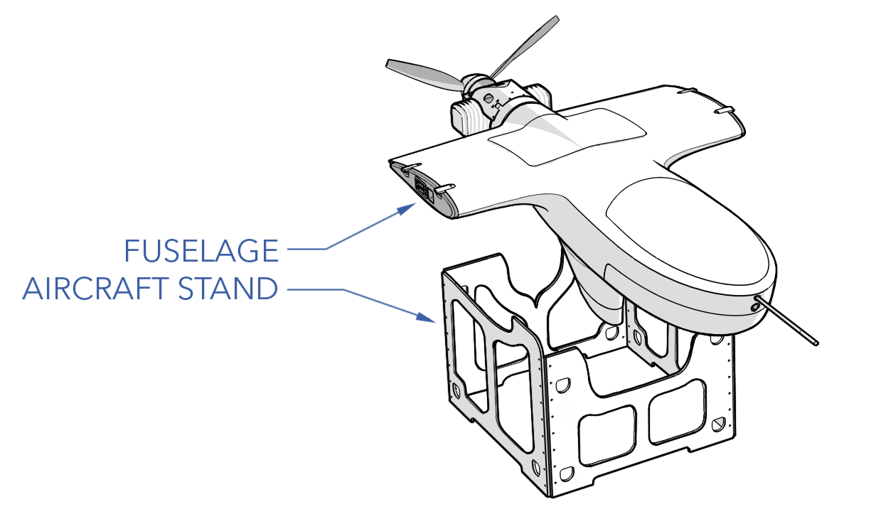
- Remove the fuselage from the case and place it on the aircraft stand. Ensure the aircraft switches remain clear of the aircraft stand.
- Remove the wing spars from the case and insert into the fuselage. The wing spars are not directional or side-specific.
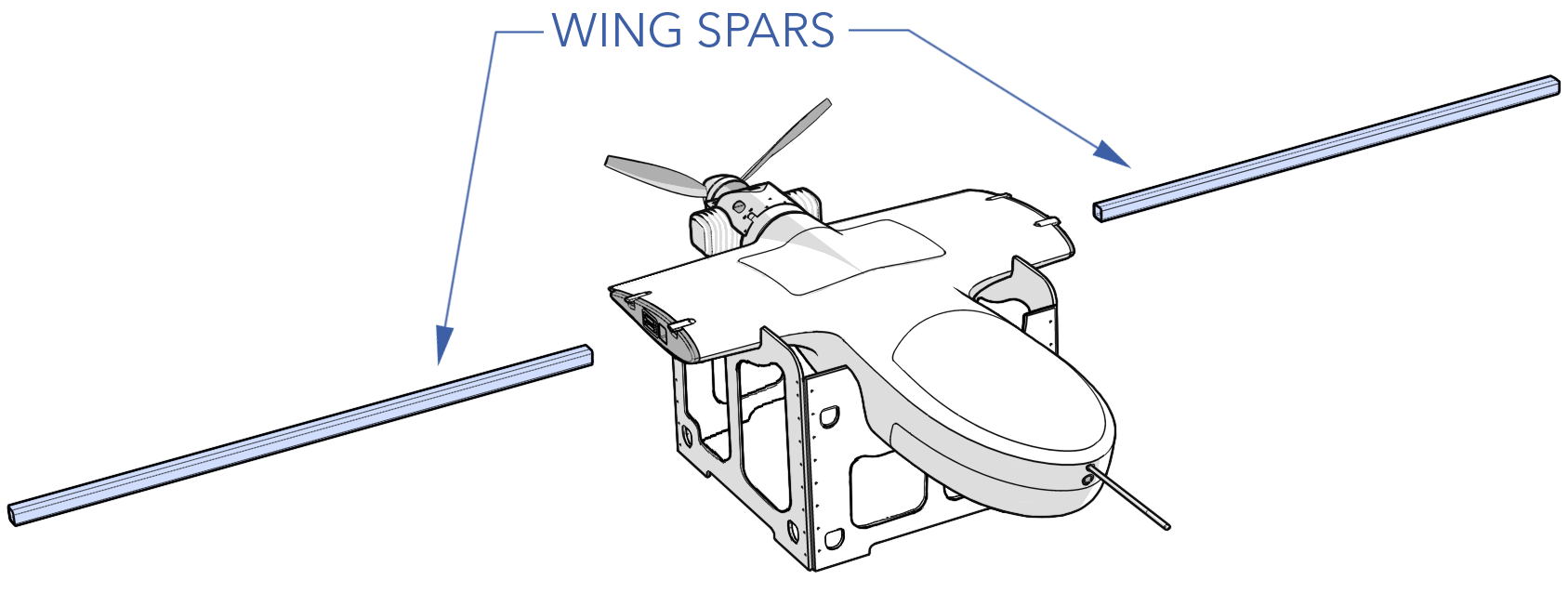
- Remove the right boom from the case and slide it onto the right wing spar while supporting the rear of the boom. Do not leave the boom supported on the spar alone, doing so may twist and splinter the wing spar. Slide the boom towards the fuselage until the two cup joints properly align. Firmly press the boom and fuselage together. Using both hands, simultaneously close both draw latches to ensure a positive connection between the fuselage and boom.
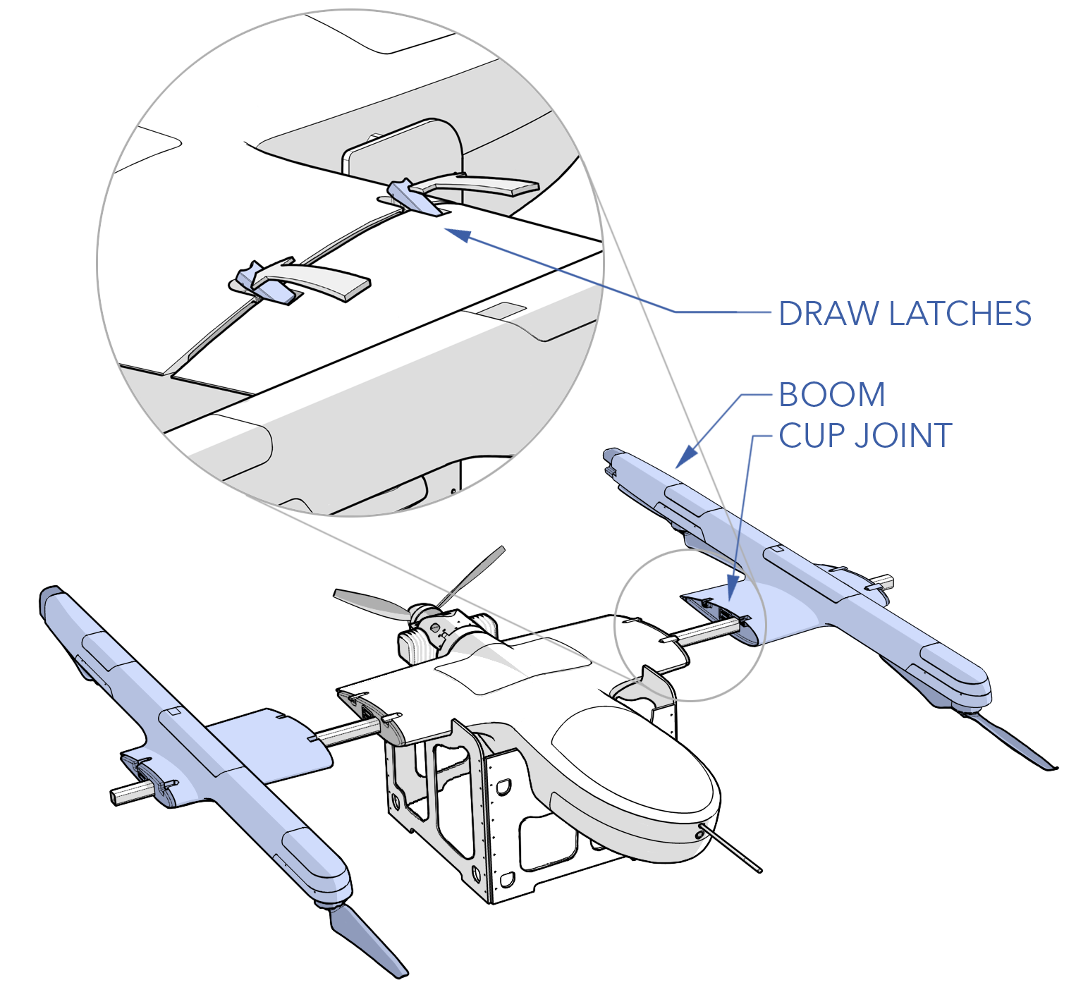
- Assemble the left boom with the same procedure as the right.
- Remove the right and left tail sections from the case. Align the cup joint located on each elevator and firmly join the two halves together. Close the draw latch to secure the two sections together.
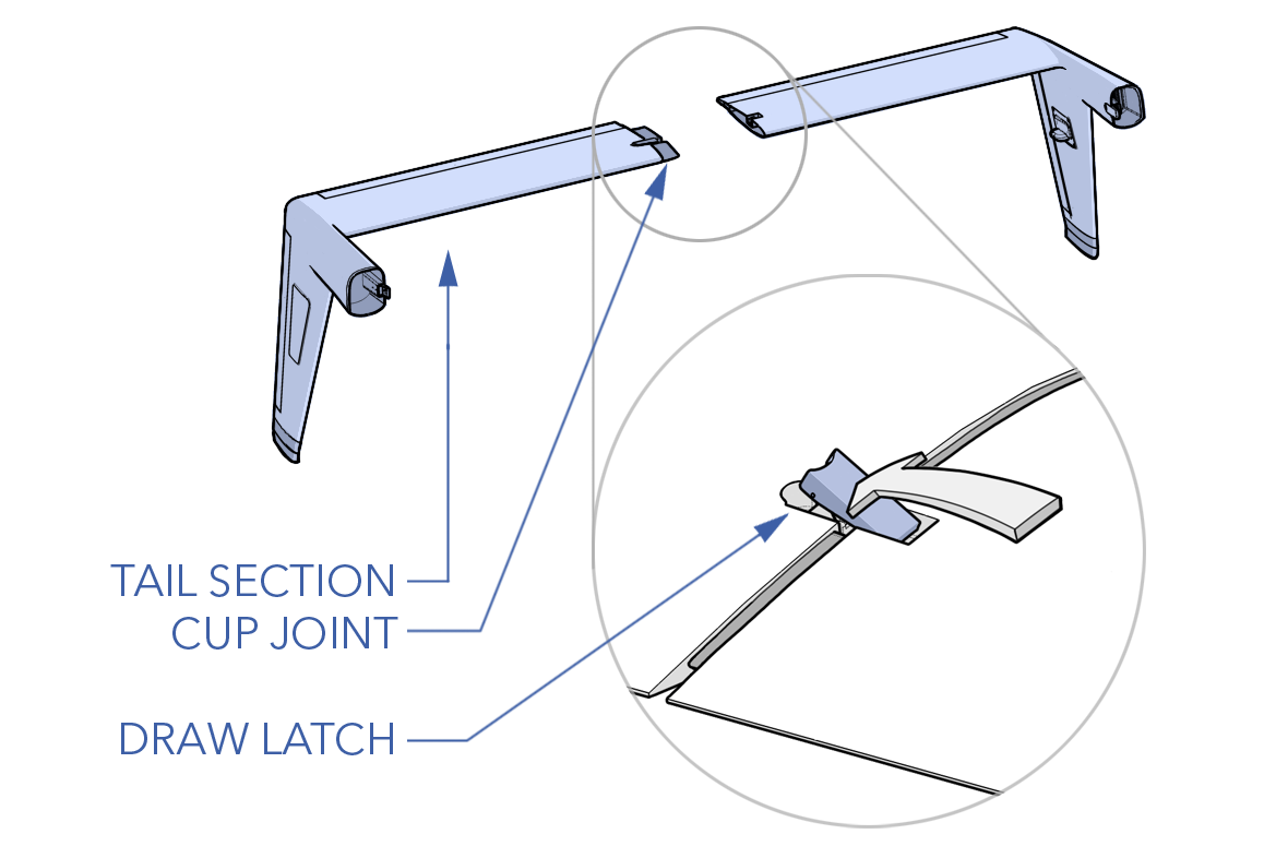
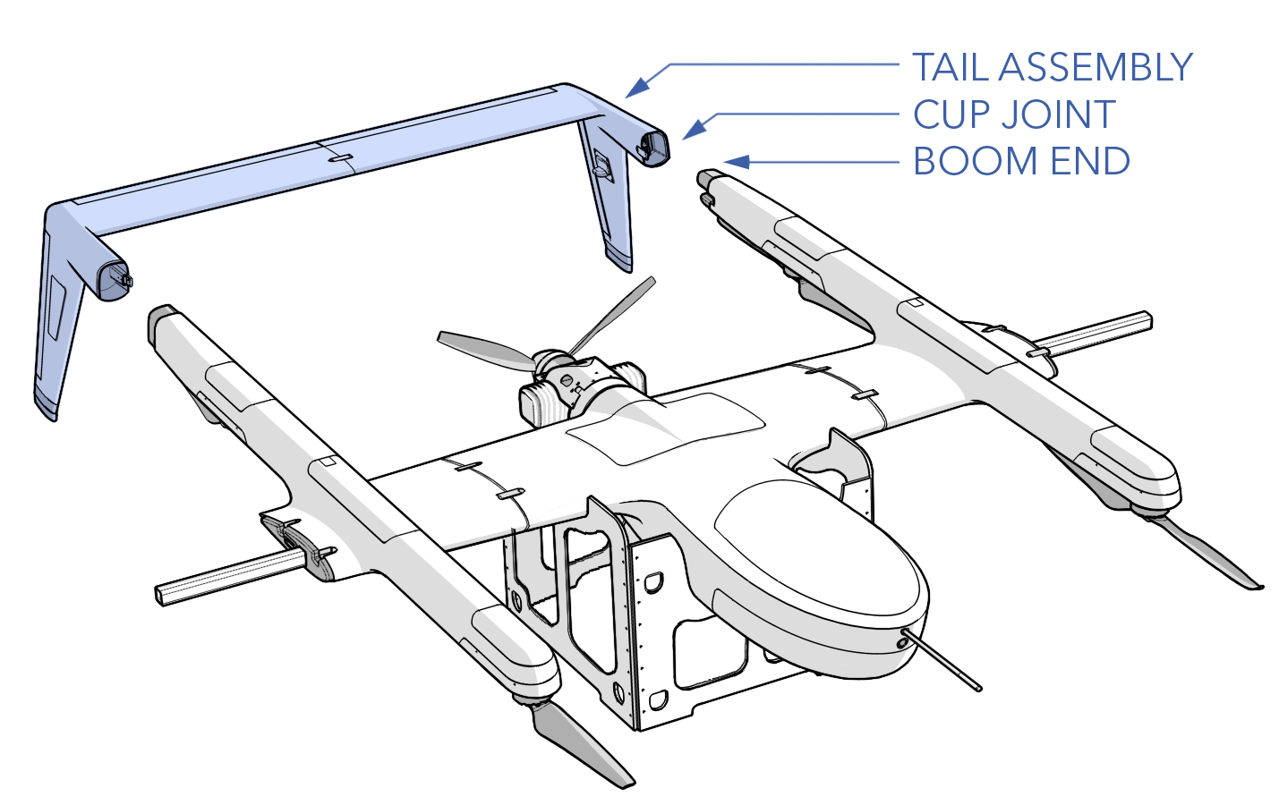
- Align the cup joints on the booms with the cup joints on the tail assembly. Slide the tail assembly onto the boom ends. Ensure both sides are mated simultaneously to prevent stress on the cup joints and connectors. Close the draw latch on each side to secure the tail assembly to the aircraft.
- Remove the right wing from the case and slide it onto the right wing spar while supporting the weight of the wing. Do not leave the wing supported on the spar alone, doing so may twist and splinter the wing spar. Slide the wing towards the boom until the two cup joints properly align. Firmly press the wing against the aircraft. Using both hands, simultaneously close both draw latches to ensure a positive connection between the wing and aircraft.
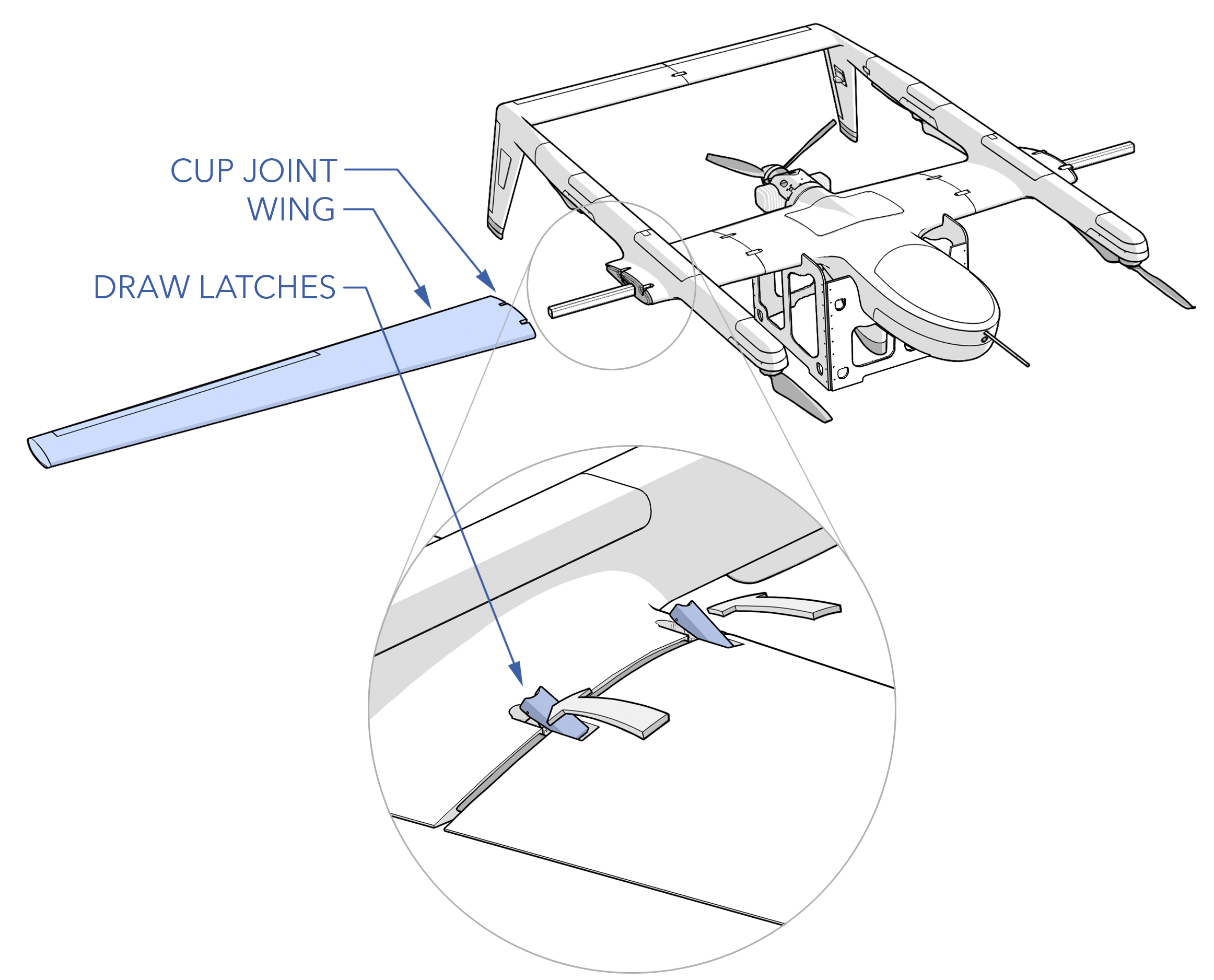
- Assemble the left wing with the same procedure as the right.
- Install the avionics battery within the fuselage. Ensure the battery is fully charged (>29 volts) and secured to the mounting tray. Do not connect the battery at this point.
- Install the VPS batteries into each boom. Ensure each battery is fully charged (>58 volts). Leave the battery covers open. Do not connect the batteries at this point.
Connecting the VPS batteries before the aircraft is powered on may damage the VPS circuitry.
- Lift the aircraft from the stand and move to the takeoff location. Do not lift by any external antennas or control surfaces.
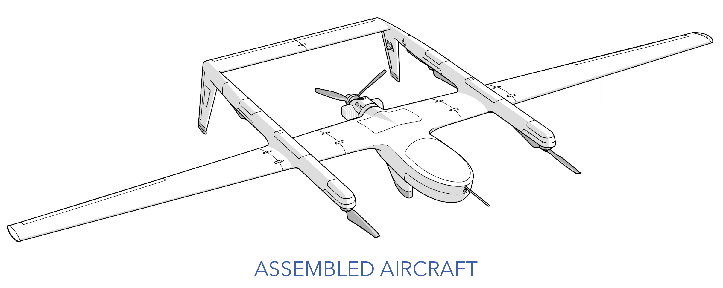
Close the transport case lid after aircraft assembly to prevent dust ingress.
Payload - Install
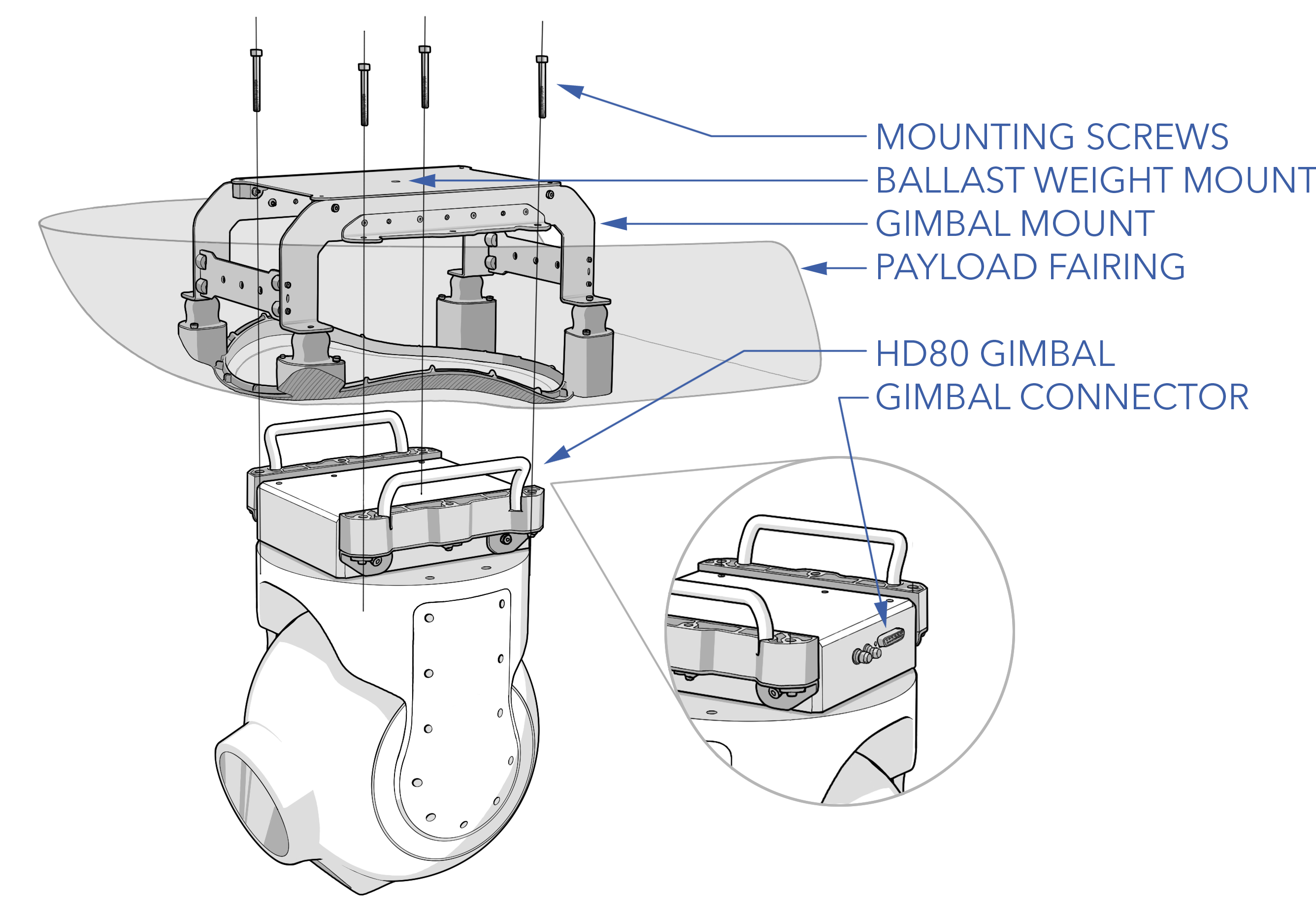
Install the payload as necessary. Check the mounting integrity of any attached payload. Inspect for damage. Verify any necessary wiring harness is connected and secure. Remove all RBFI (remove before flight items) such as pitot tube covers, optical lens caps, dust covers, etc.
Aircraft - Inspect
This step is to identify damage and/or irregularities to the airframe, payload, and subcomponents that may have been caused by previous flights, maintenance, transportation, environmental, or from normal wear and aging.
Airframe
Confirm all fasteners are fully tightened. Many critical fasteners have torque stripe applied to the screw head. Ensure that the torque stripe is not broken where visible.
Inspect the fuselage, booms, tail sections, and wings for cracks or fractures in the composite structure. Inspect the cup joints and joint connectors for damage. Inspect the control surfaces and actuators for damage and mounting security.
Ensure all hatches are secure.
Refer to the Airframe Section for a more detailed inspection and maintenance procedure.
Landing Gear
Ensure each foam landing foot is present, not damaged, and securely attached.
Refer to the Landing Gear Section for a more detailed inspection procedure or if damage is found.
Antennas
Verify that all antennas (IP radio, GPS, transponder) are securely mounted and that all RF connections are fastened.
VPS
Ensure each motor physically spins freely without signs of grinding, clicking, or irregular movement. A well-functioning motor should rotate smoothly, with the only noticeable sensation being the typical cogging of the motor magnets.
Check each of the four VPS propellers for cracks, chips, fractures, etc. Ensure each propeller is securely attached to the motor by observing that unbroken torque stripe is present on the propeller screws.
Refer to the VPS Maintenance Section for a more detailed inspection procedure or if damage is found.
FPS
Check the FPS propeller for cracks, chips, fractures, etc. Confirm the propeller is secure by grasping the propeller blades and gently rocking it. Inspect the spinner for damage and verify the spinner bolt is tight.
Inspect the torque stripe integrity on the engine latch bolts. Firmly grab the engine and rock in all directions. The motor mounts should feel smooth and resist movement. Visually inspect the mounts for damage such as material degradation, cracks, or other damage.
Torque the muffler bolts to 60 in/lbs. Inspect each muffler support bracket and fastener for tightness and security. Verify that each muffler gasket is present and intact with no signs of an exhaust leak.
Refer to the FPS Maintenance Section for a more detailed inspection procedure or if damage is found.
Pitot Tube - Check
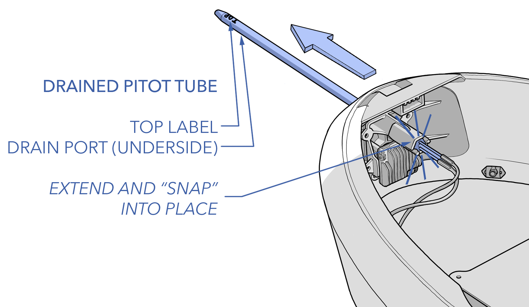
Extend the pitot tube until it snaps into place. Verify that the pitot is not bent. If using the drained pitot tube, verify that the label "TOP" faces up towards the sky and that the drain port is below. Verify that the pitot tube is free of obstructions. Verify that the pitot tubing in the fuselage is free of kinks. Verify that the hoses are fully inserted into the quick-disconnect fittings located on the avionics stack and the barbs located on the backside of the pitot tube itself.
Aircraft Switches - Off
Ensure all aircraft switches are off (down).
Aircraft - Fuel
Fuel the aircraft with the appropriate amount of gasoline needed for the flight, including an hour reserve of 2.5 lbs (1.13 kg).
Refer to the Fueling Section for detailed fueling and mixing instructions.
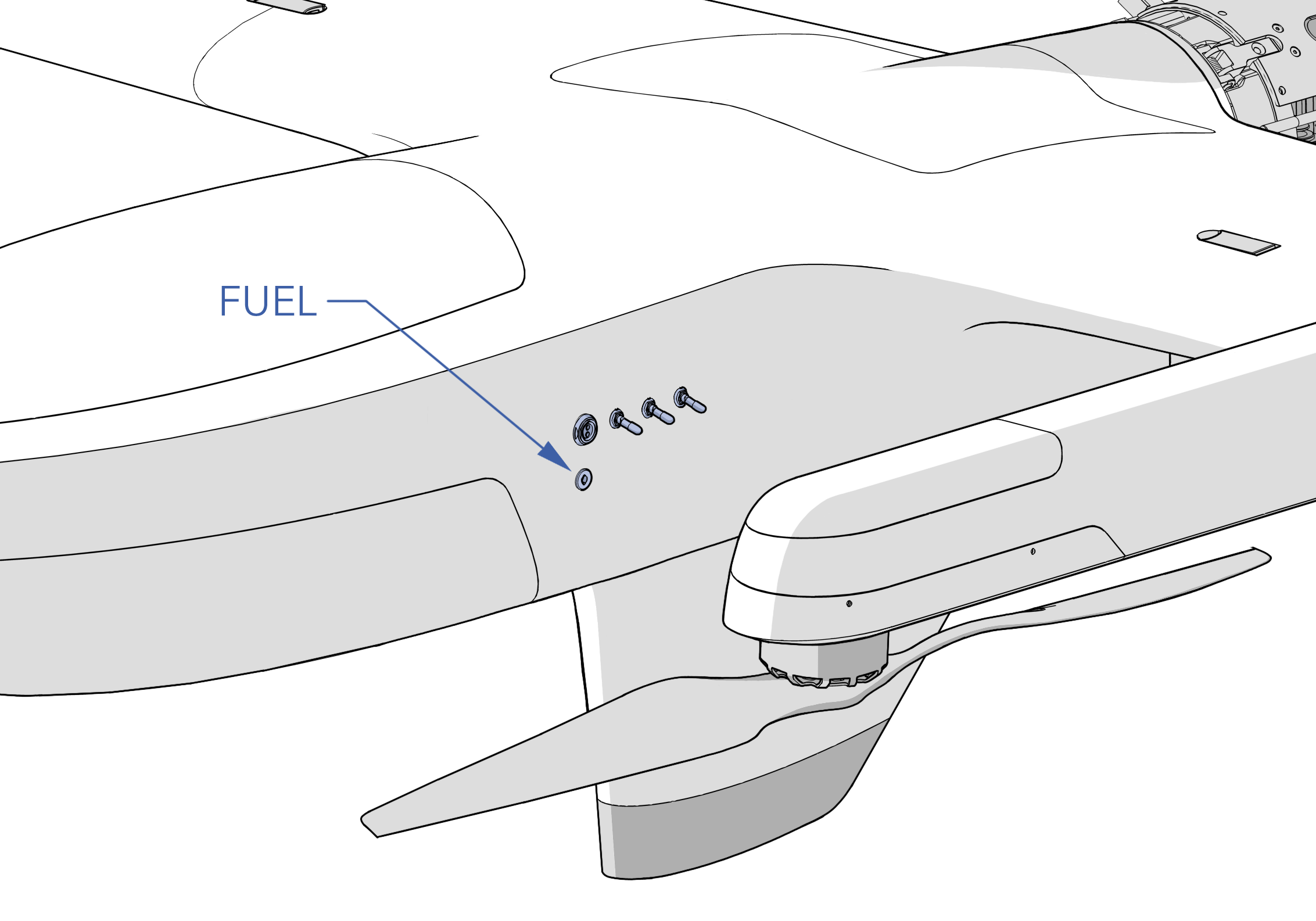
The aircraft will under-report the amount of fuel you put in by about 1 lb (0.45 kg) because the fuel remaining at that level is too low for the fuel sensor to report.
Weight and Balance - Verify
Verify that the aircraft is balanced within the acceptable CG range and that the MTOW does not exceed 130 lbs (60 kg).
Refer to the Weight and Balance Section for detailed balancing instructions.
Avionics Battery - Connect
Connect the avionics battery.
Aircraft Power - On
Power on the aircraft by flipping the main power switch on.
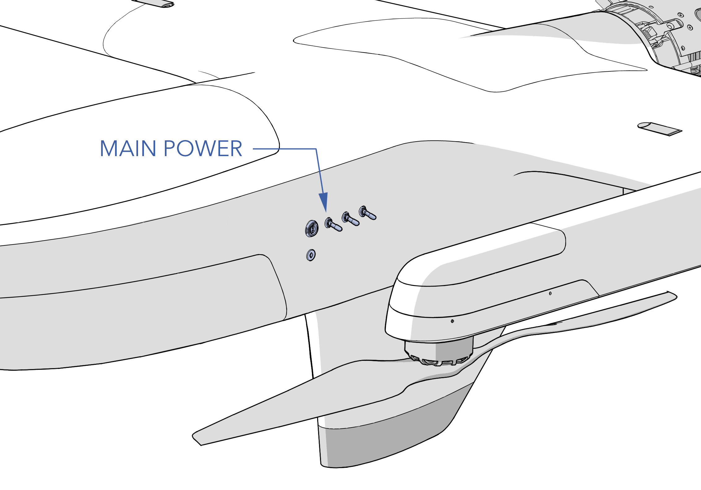
As soon as the aircraft is on, the autopilot and sensors will begin to initialize. Avoid moving the aircraft during these first few seconds.
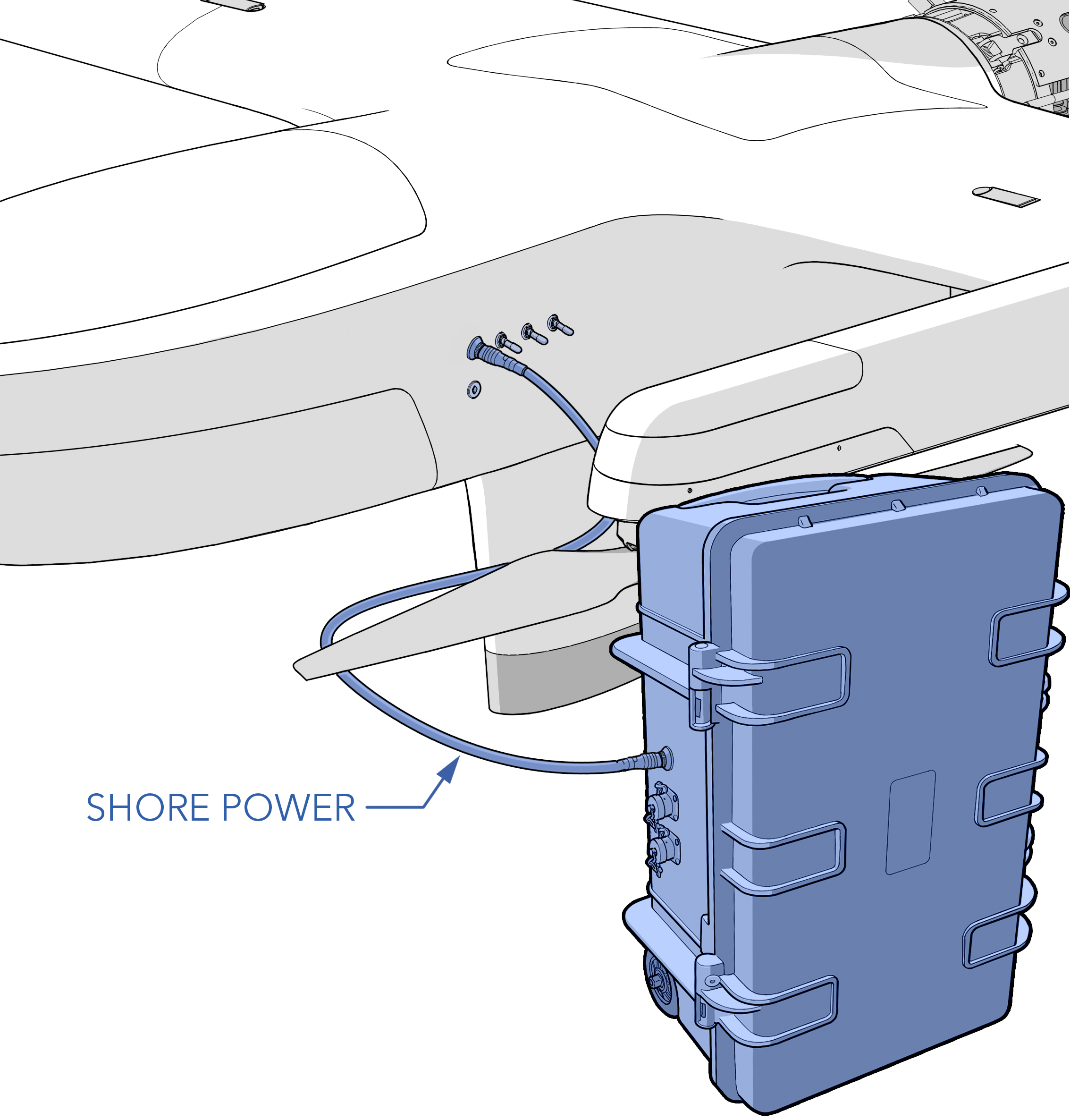
Shore Power - On and Connect
Connect shore power from the APS to the aircraft.
Canopy - Install
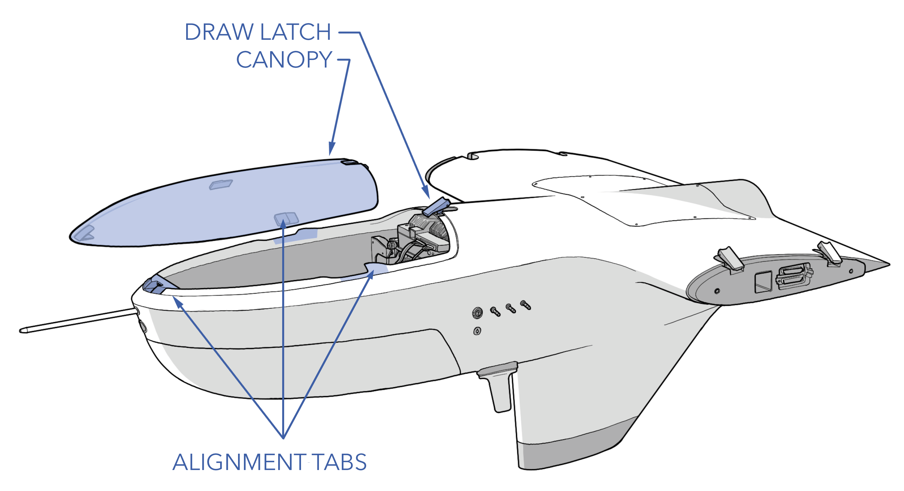
Install the canopy onto the fuselage.
Line-up the three tabs on the canopy (front, left, right) with the tabs on the fuselage and slide the canopy back. Secure the canopy in place with the draw latch.
VPS Batteries - Connect
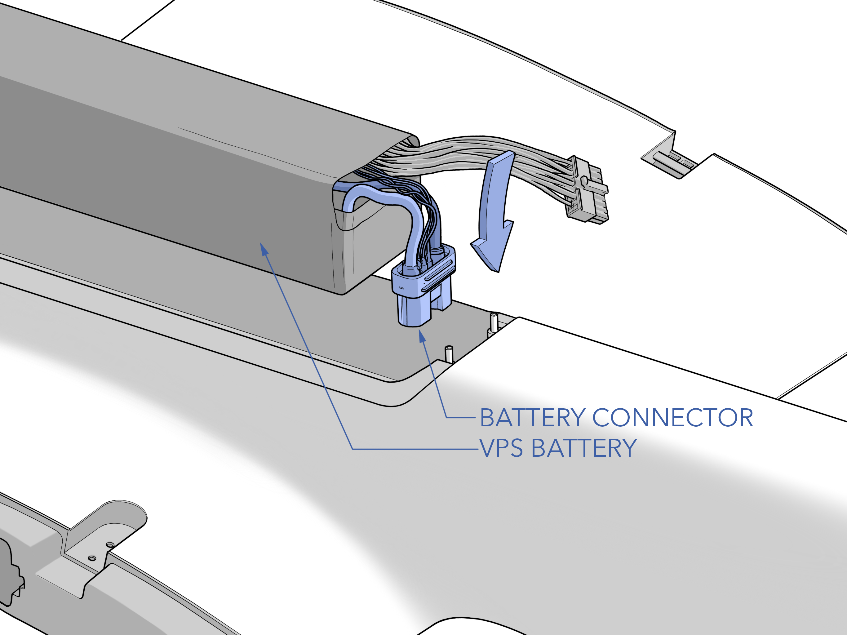
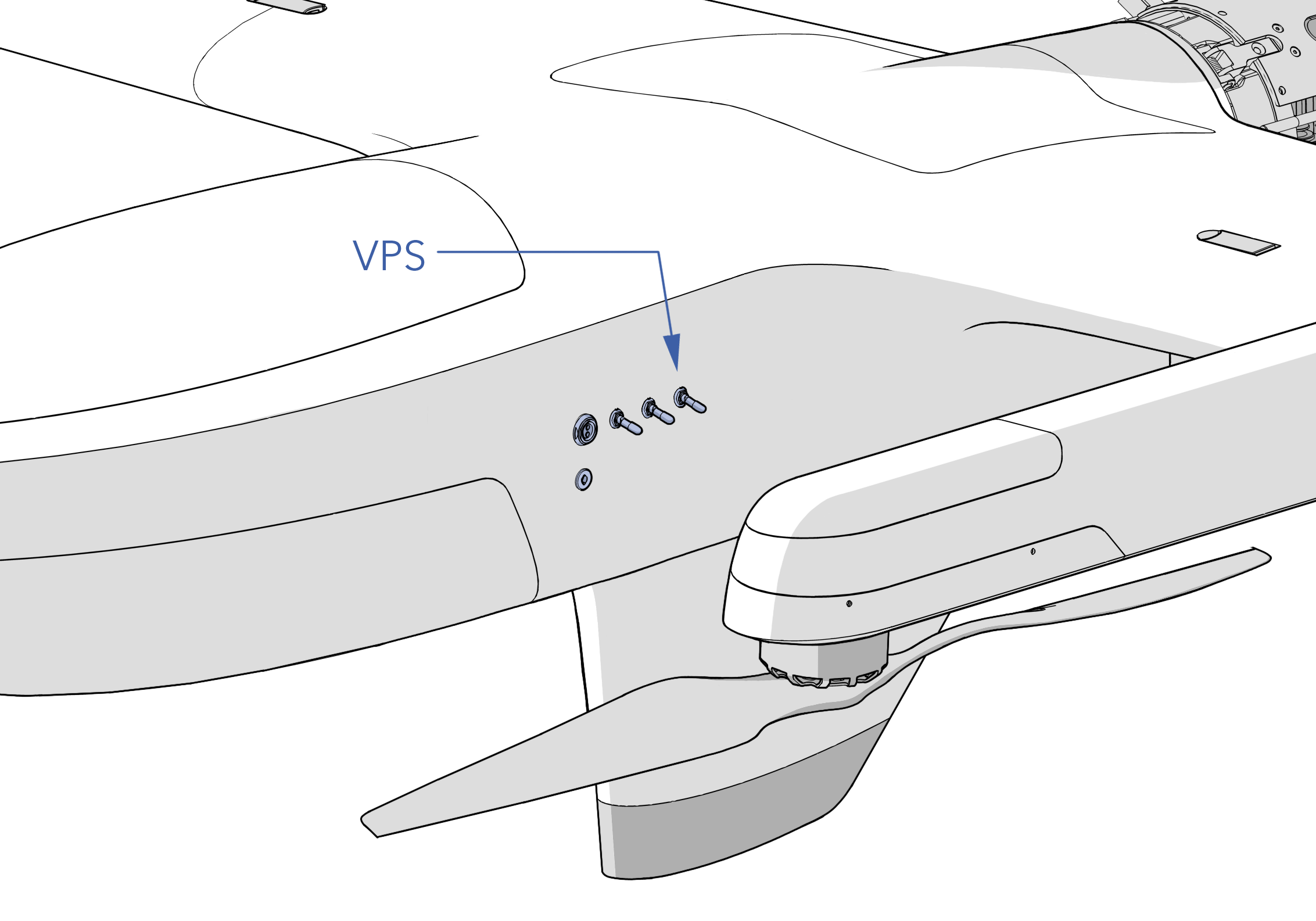
Connect each VPS battery to the boom. Ensure the battery connector is fully seated.
Close and latch the battery hatches. Ensure no wires are pinched.
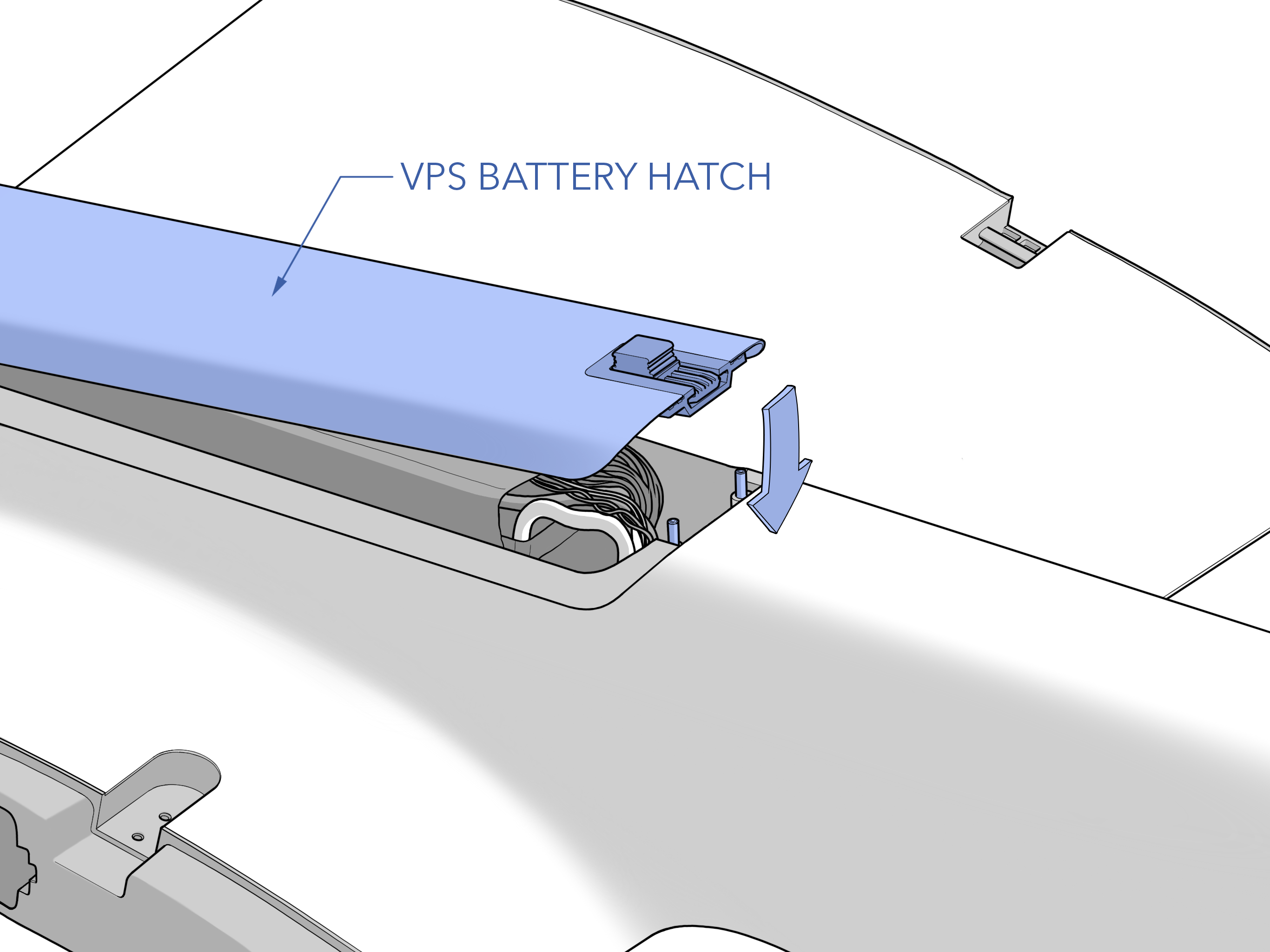
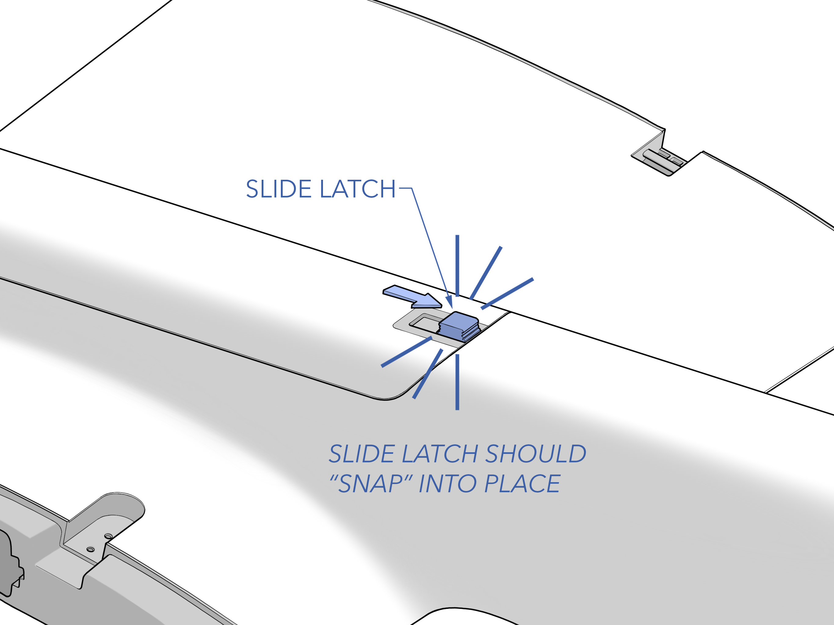
Ensure the side latch is secure. It should snap into place.
Radio Settings - Verify
Verify the radio settings are set appropriately for both the air and ground IP radio.\n\nOpen a web browser on the GCS computer and enter the ground radio's IP address (printed on the radio) to view the ground IP radio configuration page. On the homepage Under Local Radio Configuration ⇨ RF ⇨ Basic configure the Frequency, Bandwidth, Network ID, Link Distance, and Transmit Power to match the aircraft's settings and satisfy mission requirements. Repeat the same check for the aircraft radio using 192.168.xxx.87 or http://silvus-yyy.local.
xxx - Unique Aircraft ID (provided by SpektreWorks)
yyy - Aircraft Tail Number
Controller Remote Host and Model - Verify
Autopilot - Connect
From the Checklist tab in Swift GCS press Connect ⇨ UDP Client ⇨ IP Address computer-xxx.local ⇨ Port 14550
Aircraft - Disarmed
Ensure the aircraft is disarmed before proceeding. This is an automated check. If the aircraft is armed for whatever reason, you must disarm it manually.
Firmware - Check
The GCS will automatically check that the autopilot's firmware is correct and up to date. If this check fails, go to the Settings Tab ⇨ Firmware Upload in Swift GCS to update the firmware.
Refer to firmware update for more information.
Automated Parameter Checks
The GCS will automatically check that the autopilot parameters are correctly configured. If any parameters fail the check please contact info@spektreworks.com. Do not fly.
Payload Power - On
Old Mission - Clear
The existing mission on the aircraft must be cleared before a new flight. Press the Clear button on the checklist step or go to the Plan Tab ⇨ Clear WP ⇨ Clear mission on the aircraft.
Takeoff - Add
Add a takeoff at the start of the mission. Press the Add button on the checklist step.
The default takeoff altitude is 70 feet (21 meters) above home.
Refer to Mission Planning for more information on takeoff waypoints.
Sapphire has limited battery capacity for vertical flight. If the takeoff altitude is too high, the VPS battery may drain to a level that is insufficient for flight and ultimately cause the aircraft to crash. Restrict takeoff altitudes to 120 feet (30 meters) AGL or less.
Weathervaning will try to point the nose of the aircraft into the wind, but you should always point the aircraft into the wind prior to takeoff to increase performance.
Takeoff altitudes can only be planned in Above Home (AH).
Takeoff Heading - Add
From the Plan tab ⇨ Add ⇨ Waypoint to insert a takeoff heading waypoint.
As the aircraft transitions and gains airspeed, it starts navigating and climbing to the next waypoint. Add a takeoff heading waypoint to steer the aircraft away from obstacles that may be within the transition radius. Place the takeoff heading waypoint 1,500 feet (460 meters) from home, in the direction you want to fly, and 20 ft (6 m) higher than the transition altitude.
Mission - Create
Create or load a mission from the Plan Tab.
Refer to mission planning for more information on waypoints.
The aircraft will climb or descend enroute between waypoints. The autopilot calculates a slope between two waypoints and plans to achieve its altitude as it reaches the next waypoint. For example, if your next waypoint is one mile away and 1,000 feet higher, the aircraft will gradually climb along that one mile route. The aircraft will not fly to a waypoint and then climb or descend in circles.
Landing - Add
From the Plan tab ⇨ Add ⇨ Land to insert the landing pattern at the end of the mission.
The default transition altitude is 70 feet (21 meters) above home.
Refer to mission planning for more information on landing patterns.
Sapphire has limited battery capacity for vertical flight. If the landing altitude is too high, the VPS battery may drain to a level that is insufficient for flight and ultimately cause the aircraft to crash. Restrict landing altitudes to 120 feet (30 meters) AGL or less.
Always plan the final leg of a pattern landing into the wind when possible. A landing with a strong crosswind components or tailwind will cause the aircraft to overshoot and may overwhelm VPS authority during transition.
With an autonomous landing, the GCS operator has no direct input on the landing after the aircraft has transitioned.
Rally Points - Add
From the Plan tab ⇨ Add ⇨ Rally to insert a rally point.
Mission - Upload
Press Upload on the checklist step, or go to the Plan Tab ⇨ Upload to upload the mission to the autopilot.
Planned and modified waypoints will appear red in the GCS until uploaded to the autopilot.
Flight Modes - Verify
Failsafes - Verify
Payload Checks Complete - Verify
Payload Power - Off
Nav Lights - Verify
Verify the navigation lights and strobes as required by the mission. To activate, go to Equipment ⇨ Nav Lights and/or IR strobe in Swift GCS on the right hand side.
The nav light board is located on each wing tip. Ensure both sides are illuminated. Each side has a nav light, strobe, and IR strobe. To check the IR strobe, turn off the visible lights and cup your hand around the light cluster to see the dim blinking red IR light.
Autopilot - Warmup
This is an automated step that waits for the autopilot to heat itself to an internal temperature of at least 104°F (40°C) for improved sensor accuracy before proceeding.
The autopilot has an internal heater to hold the IMU at a specific temperature which improves the accuracy of the sensors. Please wait for the IMU to reach the required temperature before proceeding.
Airspeed - Calibrate
This step will walk you through calibrating the airspeed sensor. First shield the pitot tube from any wind with the provided pitot tube cover. Next, press Calibrate on the Checklist Tab. Remove the pitot tube cover before testing. To conduct the test first cover the drain port with your fingertip. Next, tap and hold the pitot tube opening with your other fingertip while someone monitors the GCS. This action will trap air, increasing the sensor pressure reading. If enough air is trapped, the GCS progress bar will advance, and the step will complete automatically.
If the test fails, ensure the drain port is completely covered and retry by tapping harder. Do not wear gloves when blocking the drain port or pitot tube. If the test continues to fail, there may be a leak in the pitot-static system, a cut hose, or one of hoses may not be fully seated in a quick-disconnect fitting.
Compass Heading - Verify
Verify that the aircraft compass is pointing in the same direction as shown in the GCS. If the two headings disagree, you may need to perform a compass calibration.
Payload - On
VPS Batteries - Warmup
This is an automated step that waits for the two VPS batteries to heat up when operating during the winter.
Batteries perform better in warmer temperatures and are adversely impacted by cold weather. Although VPS batteries have built-in heaters that activate when plugged in, it is advisable to store them in a heated vehicle or trailer before flying. This stops the batteries from "cold soaking" before flight, thereby requiring significant time to warm-up.
VPS Switch - Verify Off
Verify that the VPS switch is off.
Mode - Auto
Using the hand controller, set the flight mode switch to Auto.
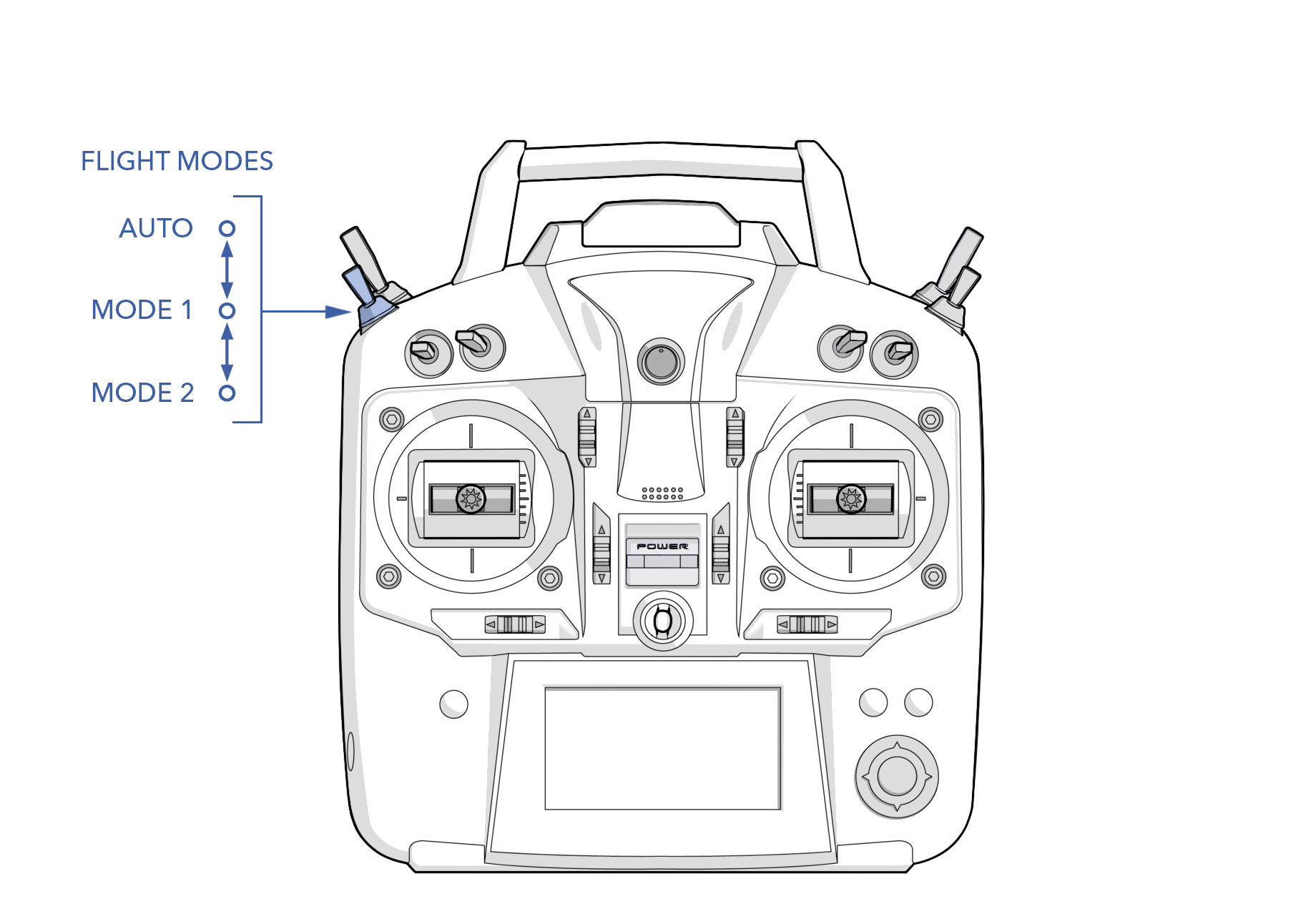
If the switch was already in the Auto position press Set on the checklist step to change the flight mode to auto. The aircraft must be in this mode to perform the control surface check.
The current flight mode is displayed on the top status bar in the GCS.
Initial Waypoint - Set
This step verifies that the initial mission item is set to a takeoff.
Control Surface - Unlock
Press Enable on the checklist step to enable control surfaces, or from the Checklist Tab ⇨ Tools ⇨ Surface Control Enable
Control Surface Response - Check
Test that the ailerons and elevators respond correctly to physically moving the aircraft.
By moving the aircraft you are testing that the autopilot is responding correctly to attitude upsets. Observe how the flight control surfaces react to upsets in roll and pitch. The control surfaces should oppose the movement in each direction. For example, when one wing lifted up, the ailerons should be trying to return the aircraft to level. The same applies to pitch.
VPS Motors - Test
This test will slowly spin each motor, starting with motor 1, 2, 3, and then 4 to test that each motor is spinning in the correct direction. After spinning, each motor should clock the propeller parallel with the boom. Press Test on the checklist step to start the spin test. Ensure the propellers are clear before proceeding.
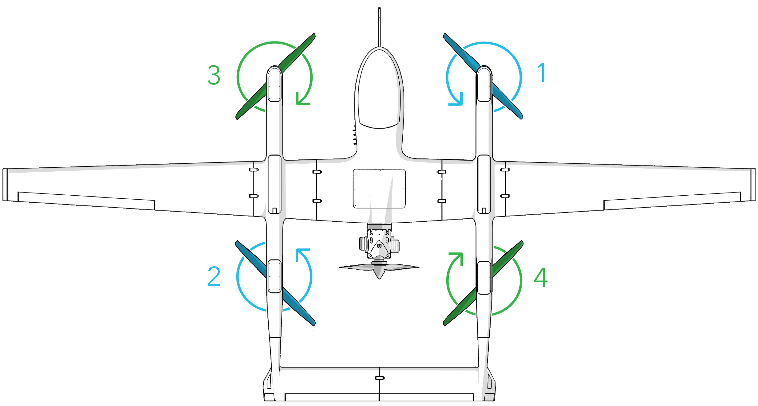
The VPS motor test will slowly rotate each propeller. Ensure all personnel are clear of the propellers.
Mode - Manual
Press Set on the checklist step to change the flight mode to manual.
Manual Surface - Check
Throttle and Ignition - Safe
On the hand controller, ensure throttle is idle and ignition is off.
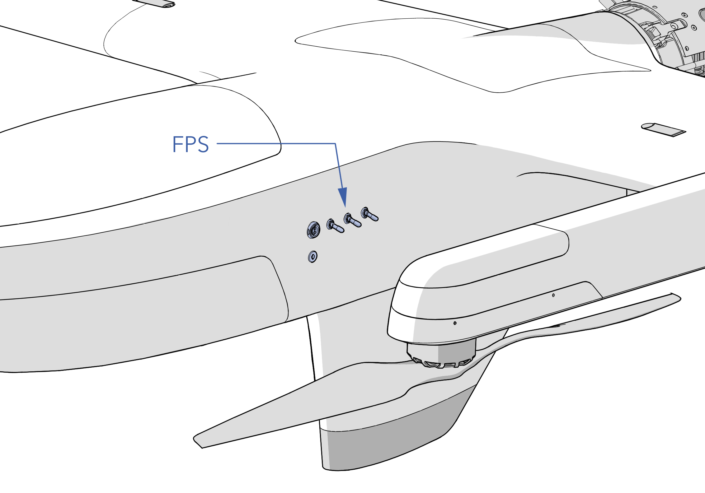
FPS Switch - On
Flip the FPS switch on to enable engine control.
Allow Disarmed Start - Enable
Press Enable on the checklist step to allow the engine to be started while the aircraft is disarmed.
This allows the engine to start while the aircraft is disarmed when using the ignition switch on the hand controller.
FPS Prop - Clear
Engine - Start
Ensure someone is bracing the front of the fuselage before starting the engine. Using the hand controller, flip the ignition switch to the ON position to start the engine. The engine will turn over using the the built-in starter. It may take a few attempts, especially in cold weather.
Do not attempt to start the engine if the avionics battery voltage is below 27.5 volts.
Starting the engine rotates the FPS propeller. Rotating propellers can cause serious injury or death. Ensure all personnel are clear of the propellers.
Engine parts, especially the muffler, will be extremely hot while running. Burns can occur on contact. Keep flammable materials away from the engine.
Shore Power - Disconnect
Disconnect shore power from the APS to the aircraft.
Payload Power - On
Engine - Warmup
Allow the engine to warm up at idle. This step will automatically pass when the cylinder head temperature (CHT) is greater than 149°F (65°C).
The aircraft maintains an idle RPM of 2,500 with a governor.
Full Throttle - Check
Using the hand controller, raise the throttle to full and hold for 7-10 seconds. The engine should not hesitate or bog down when throttle is advanced. This step will automatically pass when the engine RPM is between 6,100 to 7,000 for at least 3 seconds.
The thrust generated by the FPS propeller is enough to physically push the aircraft across the ground. Ensure someone is still bracing the front of the fuselage before going full throttle.
Sustained CHT above 270°F (130°C) will cause permanent damage to the engine. The engine will heat up very quickly while running on the ground with no airflow. Note that even after shutdown, the engine will continue to heat up as heat is transferred to the cylinder heads.
Idle - Check
Using the hand controller, lower the throttle to idle. This step will automatically pass when the engine RPM is between 2,250 to 2,750.
Mode - Auto
Press Set on the checklist step to change the flight mode to auto. The flight mode switch on the hand controller must also still be in Auto.

VPS Switch - On
Turn the VPS switch on to enable vertical motor control.

No Warnings - Verify
Ensure there are no warnings before takeoff. All warnings must be resolved. Warnings are displayed in the GCS message panel.
Refer to the Warnings Section for a detailed description of warnings, possible causes, and corrective actions.
Takeoff Clearance - Confirm
Ensure the aircraft is pointing into a headwind as the winds may have shifted during preflight. Do not takeoff if the wind speed exceeds the aircraft limit of 25 knots (12.9 m/s). Ensure the takeoff area is clear of bystanders and obstacles. Notify all crew and bystanders that the aircraft is about to takeoff.
Even within wind limits, a crosswind during takeoff can significantly hinder VPS performance. Aim for a headwind during takeoff to assist the aircraft, rather than fighting against it.
Aircraft - Takeoff
Press Takeoff on the checklist step to arm the aircraft and takeoff.
This step first arms the aircraft and then immediately commands a vertical takeoff. The aircraft will spin the VPS propellers and climb vertically to your takeoff altitude, by default 70 feet (21 meters) above the ground. During the ascent, the aircraft will weathervane into the wind for assistance. Upon reaching the takeoff altitude, the aircraft will transition to forward flight and navigate to the takeoff heading waypoint.
If the aircraft refuses to arm, it will not takeoff. The arming issue must first be resolved. Refer to the Arming Checks for a detailed description of the checks, possible causes, and corrective actions.
The VPS propellers will rotate immediately after arming the aircraft. Rotating propellers can cause serious injury or death. Ensure all personnel are clear of the propellers.
The thrust generated on takeoff and landing can generate large amounts of dust. Dust can obscure visibility, contaminate electronics, and reduce aerodynamic efficiency. Use a landing pad to reduce dust when flying from unimproved surfaces.
Before arming, the aircraft must undergo a series of automated pre-arm checks, which are distinct from preflight checks and are performed internally by the autopilot. Failed pre-arm checks will be displayed in the message panel of the GCS. See Arming Checks for a detailed description of pre-arm checks, possible causes, and corrective actions.
Arming finalizes the home location.