Antenna Tracker
This is appendix is intended as a supplemental guide only. Refer to the TSC Mobile Tracking System User Manual 3.X before operating.
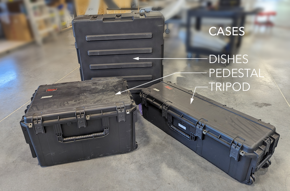
- The MTS 3.X antenna tracker is transported in three rugged cases. One case for the antenna dishes, one for the pedestal (pan/tilt) and radio, and one case for the tripod.
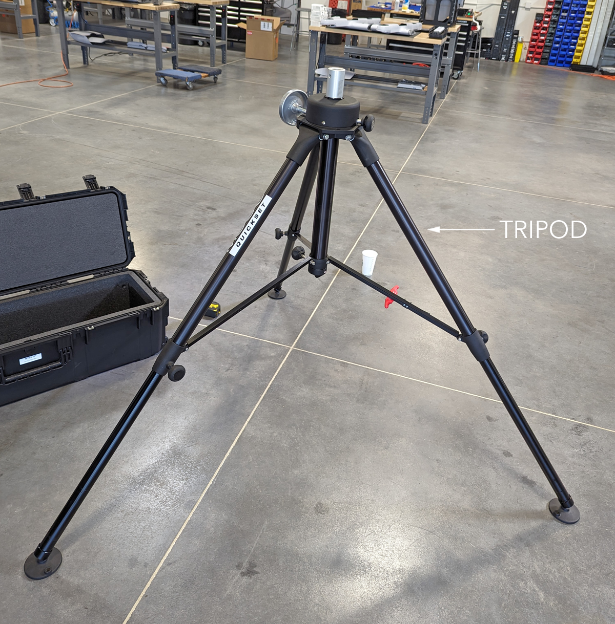
- Unpack the tripod. Place the tripod on stable, level ground, in a location that will offer clear LOS between the antenna tracker and the aircraft.
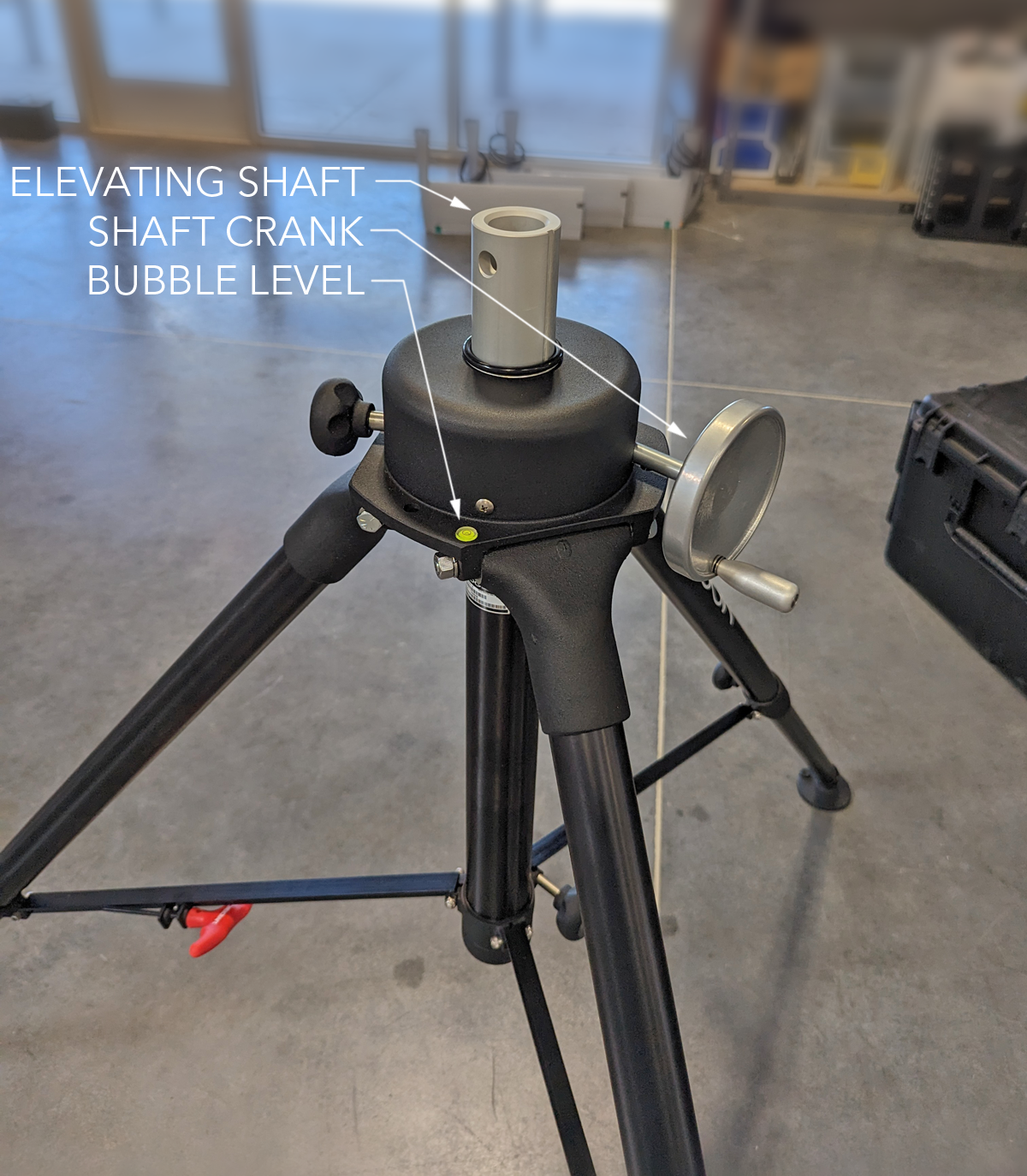
- Adjust the tripod legs until the bubble level is centered. Elevate the tripod shaft a few inches using the shaft crank.
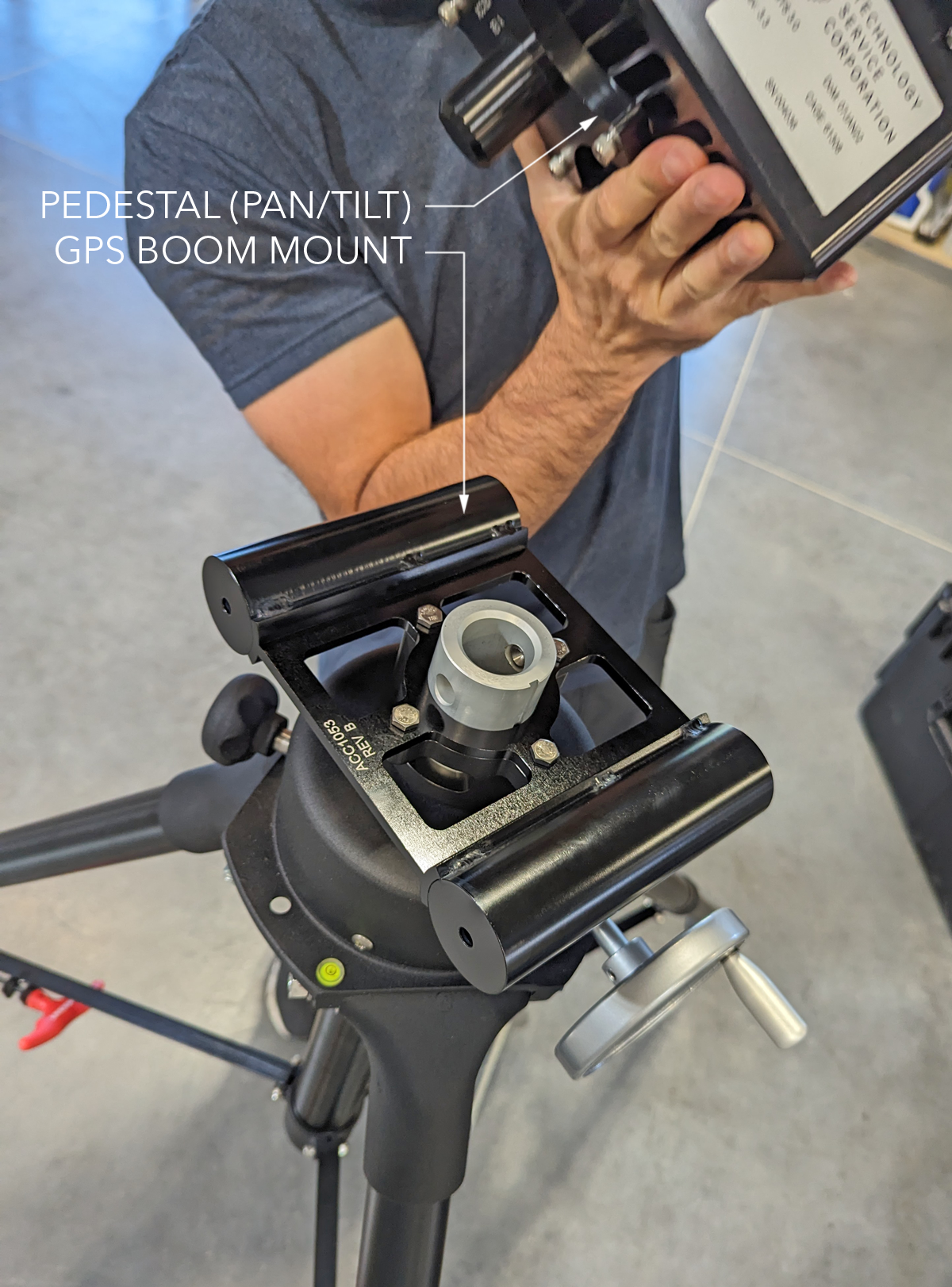
- Slide the GPS boom mount over the tripod shaft. Then place the pedestal atop the tripod.
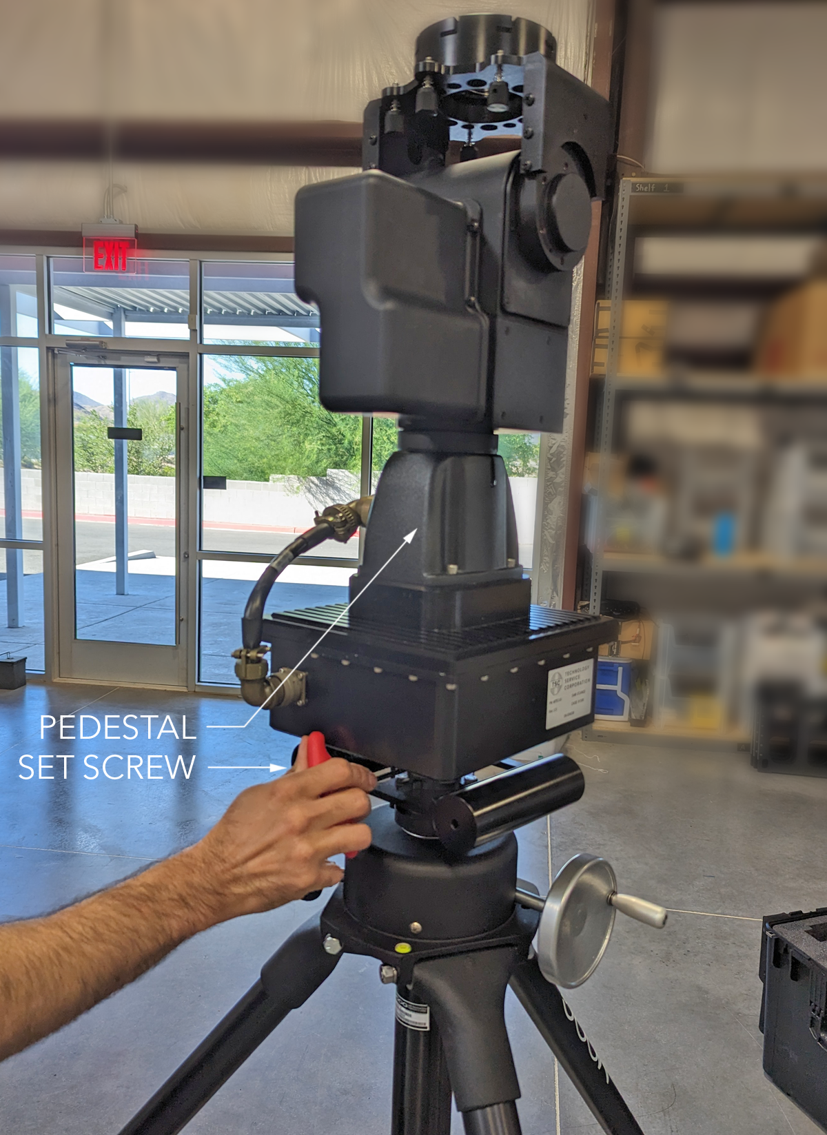
- Tighten down the pedestal set screw onto the tripod shaft using the attached hex key. You may need to raise the tripod shaft if you can not reach the set screw.
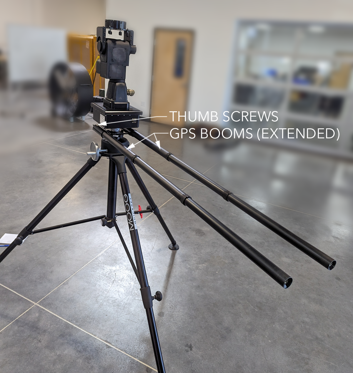
- Insert the two GPS booms into the boom mount on the tripod. Secure each boom to the mount with a thumb screw. Extend each boom.
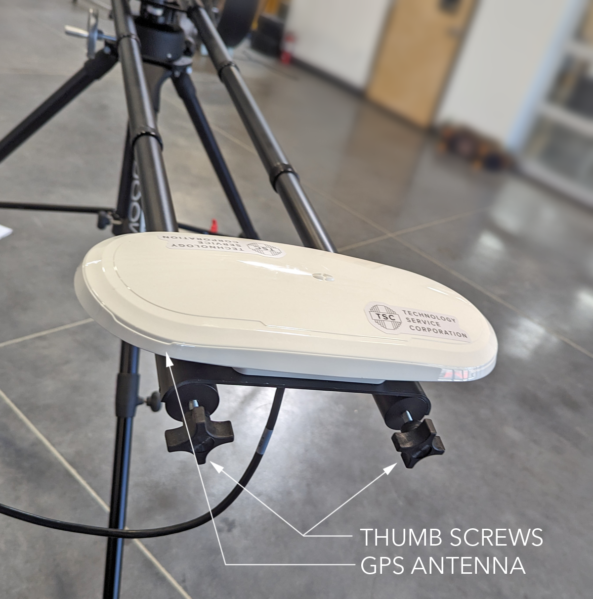
- Slide the GPS antenna onto the extend booms. Ensure the GPS antenna faces upward. Secure the GPS mount with two thumb screws.
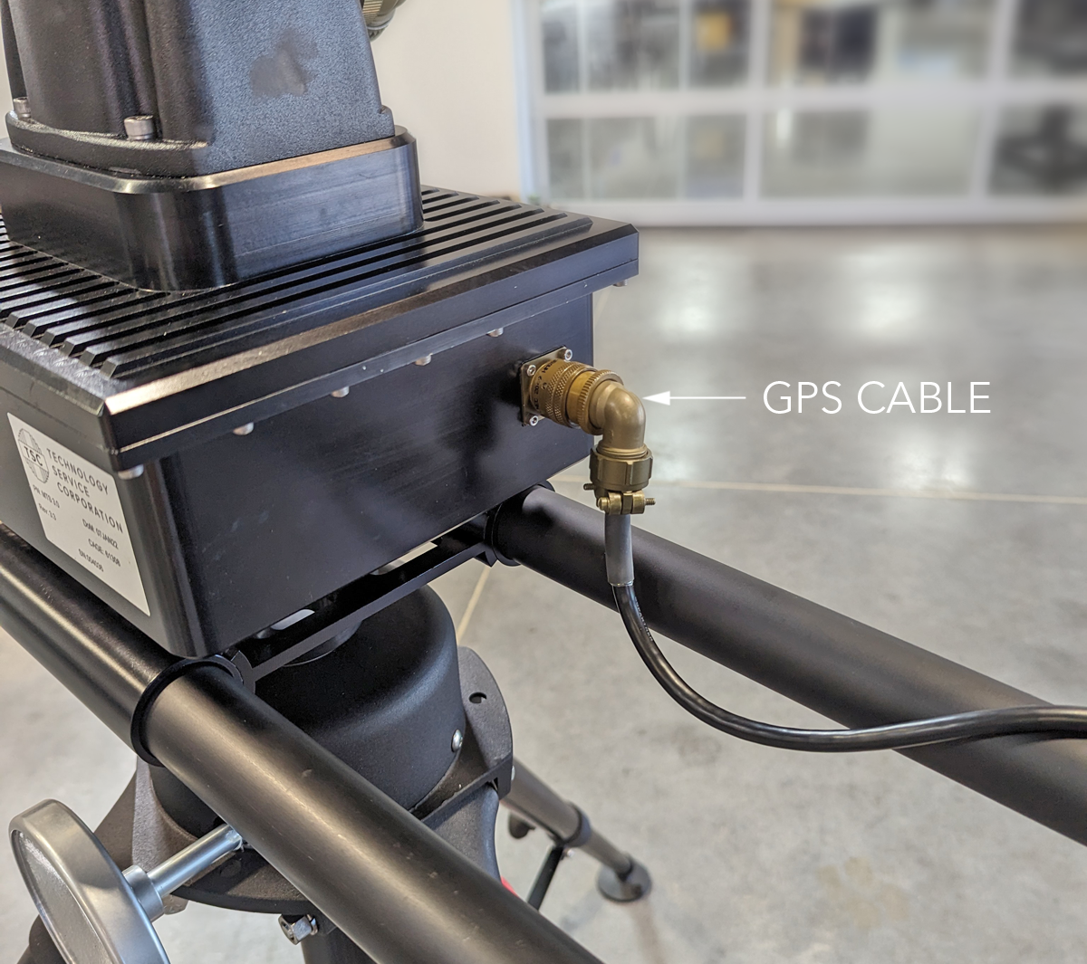
- Loosely twist the GPS cable along the length of one boom before connecting it to the pedestal.
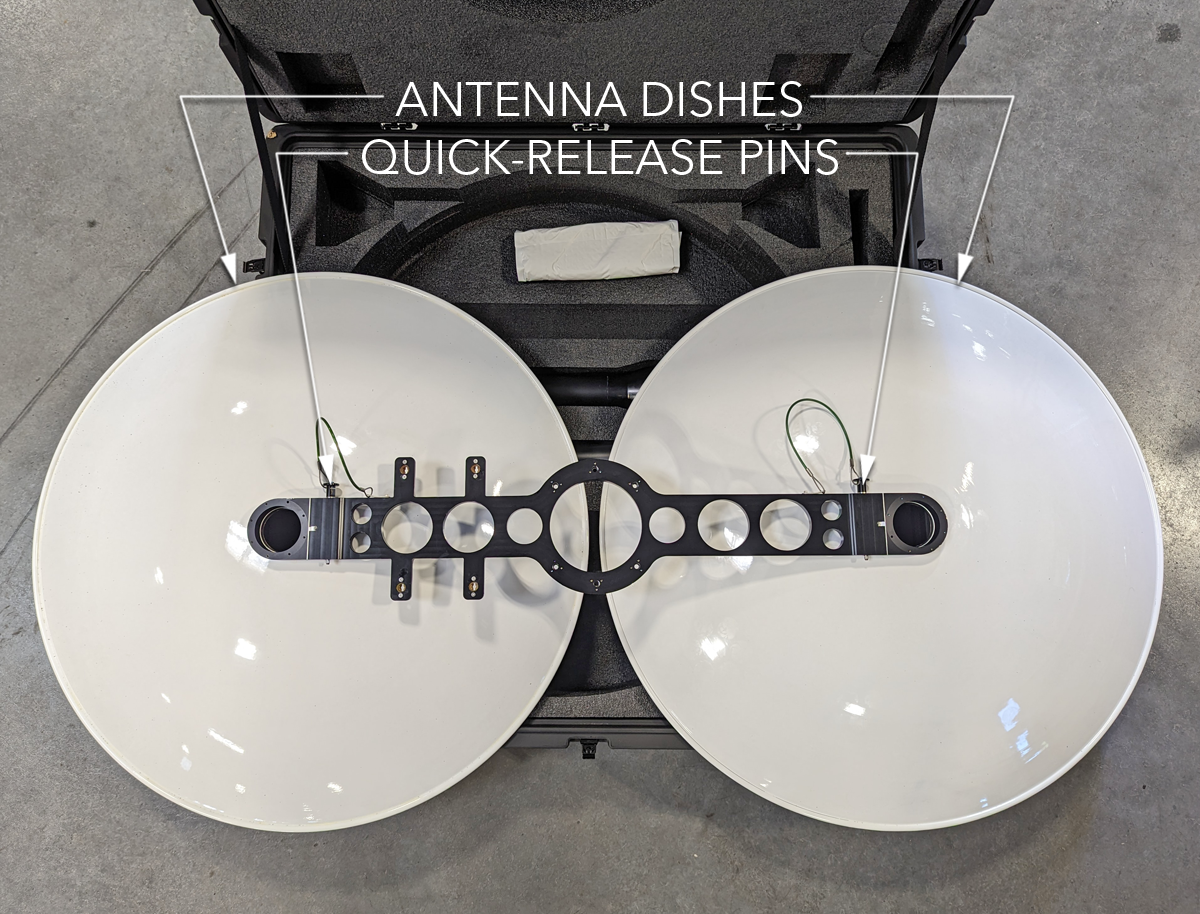
- Unpack the two antenna dishes. Place each dish face down on a soft surface. Secure each dish to the mounting bracket with the quick-release pin.
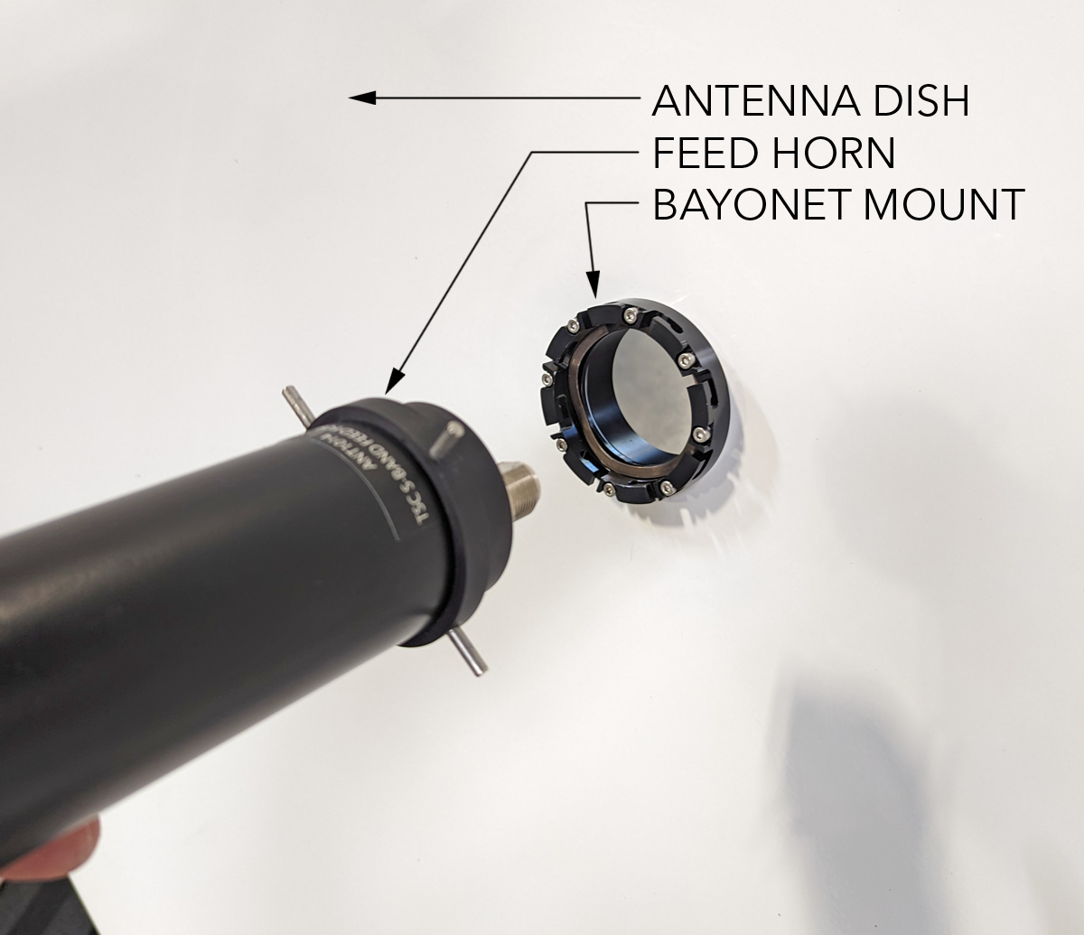
- Insert a feed horn into the center of each antenna dish using the bayonet mount. Ensure the polarization is correct.
- If using two dishes, polarize one feed horn vertically and one at a 45 degree angle.
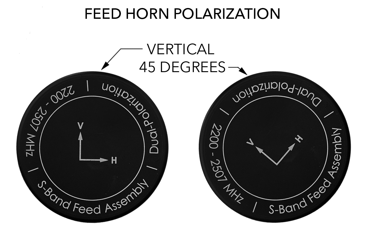
- Carefully place the assembled dishes atop the pedestal. Ensure the feed horn polarization arrows will be facing the sky during normal operation.
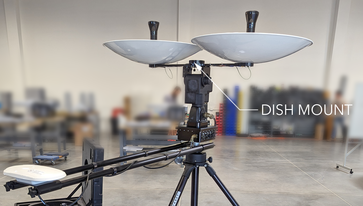
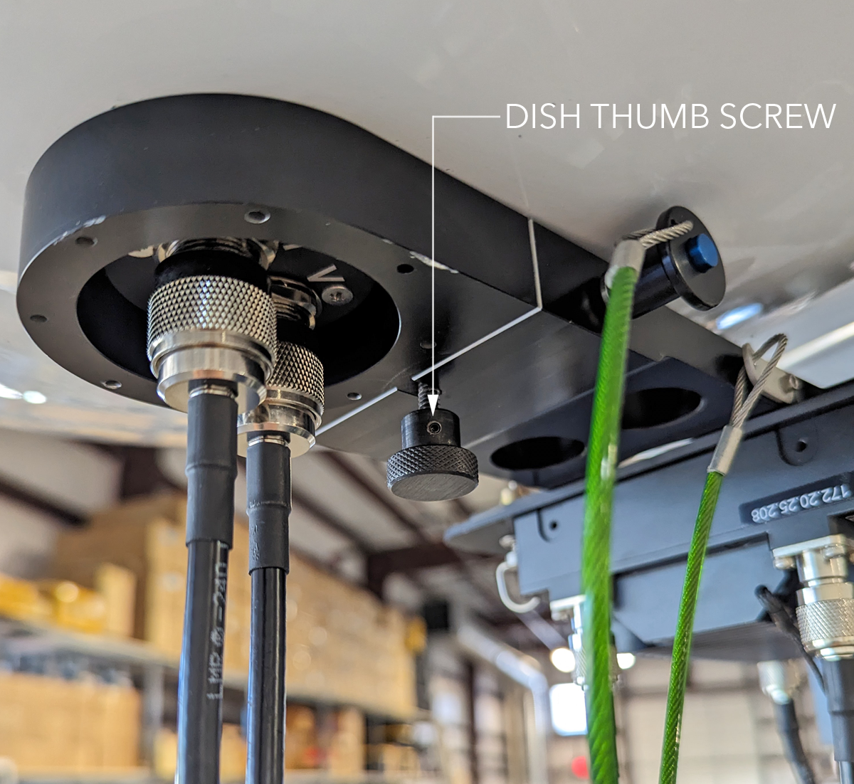
- Fasten a thumb screw behind each antenna dish. Ensure the button on the quick-release pin will be facing the sky during normal operation.
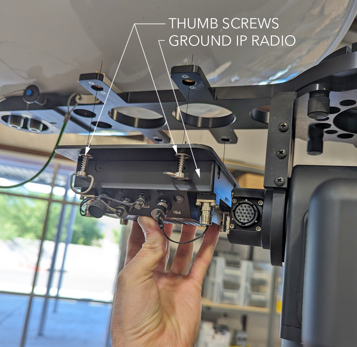
- Attach the ground IP radio to the backside of the antenna dish mount. Secure the radio with the four captive screws.
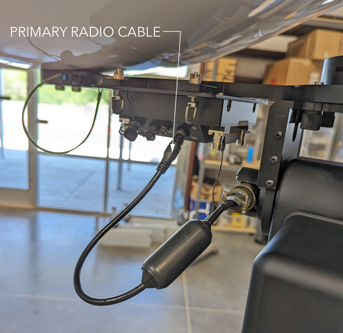
- Connect the primary radio cable between the radio and the pedestal. Route the cable such that it is not strained or pinched during normal operation.
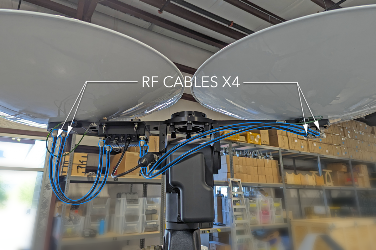
- Connect the four RF cables between the radio and the dishes. Route the cables such that they are not strained or pinched during normal operation.
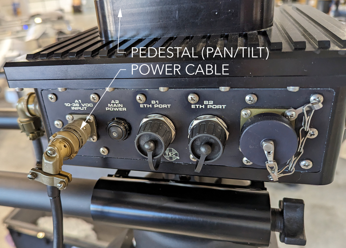
- Connect the power cable to the pedestal.
